Hi, very good visualization.
You almost got it right. In MantiumWFlow a monitoring_surface and a special_bc are two slightly different things.
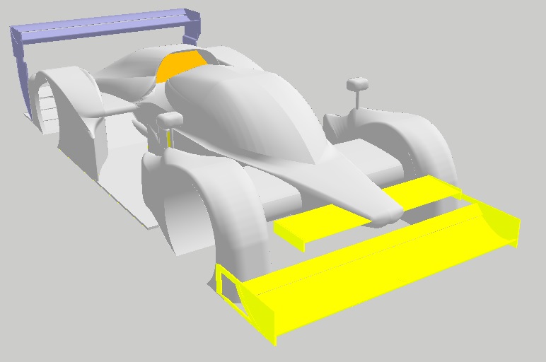
So just not to confuse anybody here. What Matteo is showing are the engine inlet and exhaust outlet surfaces. Both go into the special_bc folder. And how he is showing it is exactly how it should be done. The engine inlet surface is ahead of any other geometry and corresponds to the inlet scoop. He did the same on the exhaust. By constructing the geometry this way the vehicle body is closed and there are no openings at the engine inlet or exhaust outlet even if you would somehow forget to add these two special surfaces. By keeping a distance of about 50mm there is no chance that cells of the volume mesh get snapped to the wrong surface.
- Login or Register
No account yet? Sign up