Open Source Racecar

Post here information about your own engineering projects, including but not limited to building your own car or designing a virtual car through CAD.
cdsavage
19
Joined: 25 Apr 2010, 13:28

Re: Open Source Racecar

Post

I've had a go at doing some bodywork - the rear is based on the drawing from MileticDesign. PM me if you would like to have a look at the step file.

Image
Image
Image

User avatar
andylaurence
123
Joined: 19 Jul 2011, 15:35
Contact:

Re: Open Source Racecar

Post

That's a nice looking car. The canopy looks very large though - I guess that's down to the size of the car vs the passengers.

User avatar
Tim.Wright
330
Joined: 13 Feb 2009, 06:29

Re: Open Source Racecar

Post

I think it seems that way because the tyres are reasonably small compared to other cars. The wheels are 17". The overall height is comparable to a Lotus Elise if I remember correctly.
Not the engineer at Force India

User avatar
tomislavp4
0
Joined: 16 Jun 2006, 17:07
Location: Sweden & The Republic of Macedonia

Re: Open Source Racecar

Post

cdsavage wrote:I've had a go at doing some bodywork - the rear is based on the drawing from MileticDesign. PM me if you would like to have a look at the step file.
That's one sweet looking thing man! :) The rear bodywork looks quite steep though, adding a gourney flap at the rear would help the aerodynamics in that area. The S1 Elise has that spoiler-lookin-thingie at the back for this reason, it wasn't there in the original design but they figured they needed it.

Another thing you could improve is the quality of the surfaces. I don't know what software you used and what capabilities it has so maybe it's not possible to achieve higher quality than this.

cdsavage
19
Joined: 25 Apr 2010, 13:28

Re: Open Source Racecar

Post

tomislavp4 wrote:
cdsavage wrote:I've had a go at doing some bodywork - the rear is based on the drawing from MileticDesign. PM me if you would like to have a look at the step file.
That's one sweet looking thing man! :) The rear bodywork looks quite steep though, adding a gourney flap at the rear would help the aerodynamics in that area. The S1 Elise has that spoiler-lookin-thingie at the back for this reason, it wasn't there in the original design but they figured they needed it.

Another thing you could improve is the quality of the surfaces. I don't know what software you used and what capabilities it has so maybe it's not possible to achieve higher quality than this.
Thanks :). I havent paid too much attention to aero, mainly just enclosing the chassis components that were posted a few posts back. What do you mean exactly by the quality of the surfaces? If you mean filleting the sharp edges I've left those details out for simplicity, but I think the main surfaces are reasonably clean.

User avatar
tomislavp4
0
Joined: 16 Jun 2006, 17:07
Location: Sweden & The Republic of Macedonia

Re: Open Source Racecar

Post

cdsavage wrote:What do you mean exactly by the quality of the surfaces? If you mean filleting the sharp edges I've left those details out for simplicity, but I think the main surfaces are reasonably clean.
The transition surfaces between the main surfaces. If you are not familiar with Class A surfacing and G1/G2/G3 continuity watch the following video, it does a god job explaining the concepts http://www.youtube.com/watch?v=GSIIU03NGlY I cannot be certain without taking a closer look at the model but I think there are a few G1 transitions in it. Now I know that this is a rough first model and all, I just wanted to point that out for you.

cdsavage
19
Joined: 25 Apr 2010, 13:28

Re: Open Source Racecar

Post

tomislavp4 wrote:
cdsavage wrote:What do you mean exactly by the quality of the surfaces? If you mean filleting the sharp edges I've left those details out for simplicity, but I think the main surfaces are reasonably clean.
The transition surfaces between the main surfaces. If you are not familiar with Class A surfacing and G1/G2/G3 continuity watch the following video, it does a god job explaining the concepts http://www.youtube.com/watch?v=GSIIU03NGlY I cannot be certain without taking a closer look at the model but I think there are a few G1 transitions in it. Now I know that this is a rough first model and all, I just wanted to point that out for you.
Ive avoided G1-only transitions, as far as I can remember everything is either curvature continuous or only g0. I haven't gone to the effort of going for single-span as is common in class A but IMO at degree 5+ single span really isn't all that important. Are there any specific areas you think need work from a continuity standpoint (other than the sharp edges)?

User avatar
tomislavp4
0
Joined: 16 Jun 2006, 17:07
Location: Sweden & The Republic of Macedonia

Re: Open Source Racecar

Post

cdsavage wrote:Ive avoided G1-only transitions, as far as I can remember everything is either curvature continuous or only g0. I haven't gone to the effort of going for single-span as is common in class A but IMO at degree 5+ single span really isn't all that important. Are there any specific areas you think need work from a continuity standpoint (other than the sharp edges)?
Well, the area where the canopy meets the nose section looks like a G1 fillet in some of the pictures. Same for the transition between the roof and the sides. Are those G2? Maybe my eyes are deceiving me.

cdsavage
19
Joined: 25 Apr 2010, 13:28

Re: Open Source Racecar

Post

Certainly isnt perfect, but good enough I think. In any case I'm not sure any of the areas around the windshield would be of any use to the OP since he stated he would like to use an existing windshield from a different car.

Image
Image

Moxie
5
Joined: 06 Oct 2013, 20:58

Re: Open Source Racecar

Post

How is the project progressing. I recently stumbled upon this thread as I did research for my own retirement project. The similarities are surprising. Unfortunately I am unable to post my project on F1 tech as I am using pencil and paper. In any case, while you are working on something that looks like a modern LMP, I am thinking of a modern interpretation of a Dino.

I wont hijack your thread by going into much detail here, but maybe as time goes on I'll take digital photos of my work and post them in another thread. I have plenty of time, my retirement is 15 years away :(

User avatar
Tim.Wright
330
Joined: 13 Feb 2009, 06:29

Re: Open Source Racecar

Post

Moxie wrote:How is the project progressing. I recently stumbled upon this thread as I did research for my own retirement project. The similarities are surprising. Unfortunately I am unable to post my project on F1 tech as I am using pencil and paper. In any case, while you are working on something that looks like a modern LMP, I am thinking of a modern interpretation of a Dino.

I wont hijack your thread by going into much detail here, but maybe as time goes on I'll take digital photos of my work and post them in another thread. I have plenty of time, my retirement is 15 years away :(
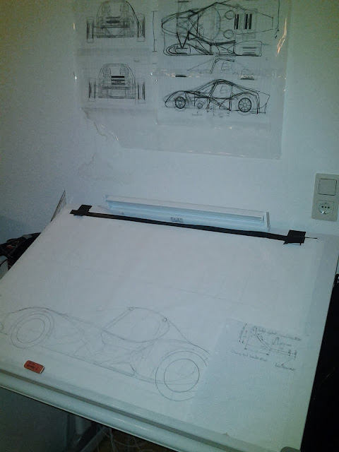
Yea, I realise its been over a year since I've actually done a meaningful update here. Not a lot has happened recently but I am working on a "new" type of interconnected suspension which I hope to post up soon. New as in, I haven't seen it done like this before, but I'm sure it has been done.

I'm also doing a fair bit of manual work like yourself:
Image

I have also made an adjustable ergo mockup for the driver's seating position. I've found something that I'm reasonably happy with in terms of the seating position, but I'm a little concerned that its too low and that the front tyres will block my field of vision too much. When I get some time I will make a 1:1 carboard tyre to place in the ergo rig and see if I can indeed have an acceptable field of vision through the tyres.
Image

I will do a post (hopefully soon) on my suspension idea. Basically its an interconnected suspension which uses a series of links instead of hydraulics to control the vertical compliance. Mainly because I'm not confident that I could design/make a hydraulic system that doesn't leak or have excessive compliance.

The system itself isn't so complicated and I'm sure its equivalent to some hydraulic system thats been done before. My system has 2 springs which control heave and roll and then a third that controls pitch. The warp stiffness is very low which was the goal of the system. I am able to get roll/warp ratios in the region of 30-50 from my initial calcs.

I'm currently working on the mathematical modelling of it so I can understand it better. So far this is a largely manual process with some pretty massive equation. I will post all of my work here and hopefully start a bit of a discussion. This is my working to arrive at the equation for the front left wheel force:
Image

Also, thanks to Miletic and cdsavage for the body contributions. They are more or less in the direction that I want.

I have uploaded my CAD model in STP format if anyone want to stuff about with it:
https://skydrive.live.com/redir?resid=5 ... 5-FdeFKqSE

Tim
Not the engineer at Force India

Greg Locock
230
Joined: 30 Jun 2012, 00:48

Re: Open Source Racecar

Post

I think if tractor drivers can plumb hydraulic systems together (one of my old jobs) then it shouldn't be too hard for you! after all you do your own brakes don't you? I'm not a huge fan of mechanical linkages in suspensions as the slop in the joints is noisy and inelegant. However it can be done - a Watts link is a perfectly good mechanism that can easily be engineered to a good standard.

Greg Locock
230
Joined: 30 Jun 2012, 00:48

Re: Open Source Racecar

Post

Subject: Open Source Racecar
Tim.Wright wrote:One thing you could probably answer. The curves for roll centre height and lateral position only match up to Adams when I do a simulation with ISO (dependent) coordinates. When I do a normal opposing wheel travel (with independent coordinates) I get a completely different result for the roll centre. And as usual the difference isn't explained properly in the Adams documentation. What is your take on this?

At the end of the day, I'm not the kind of person to get too excited about roll centre movements (especially when one calculation in adams says its at Y=10mm and the other says its at Y=-500mm) but I'd like to understand the Adams convention.
I'm just looking at your spreadsheet, very nice. I don't understand what you mean by ISO coordinates, are you using /Car?

RCH in A/Chassis is not my favourite request, in fact we don't use it routinely, we use a plot of Fz vs parallel Fy for correlation and for reporting I often stick spherical joints in and use the adams request for geometric RCH, then it gets close to the drawing board answer. In /Chassis the RCH req is a half car job, and we don't run half car any more routinely, as our K&C event has been replaced by a custom one that replicates the way our K&C rigs move, essentially holding the ground plane still and moving the body around. Since the RCH req uses velocity vectors , and the CP velocity is zero, it doesn't like the new test!

I too have never found lateral RC migration to be of interest.

User avatar
humble sabot
27
Joined: 17 Feb 2007, 10:33

Re: Open Source Racecar

Post

looking back at your spec tables, i think your fire suppression system is underweight.
the four immutable forces:
static balance
dynamic balance
static imbalance
dynamic imbalance

User avatar
Tim.Wright
330
Joined: 13 Feb 2009, 06:29

Re: Open Source Racecar

Post

humble sabot wrote:looking back at your spec tables, i think your fire suppression system is underweight.
Yea well Id sort of just accounted for a for a fire extinguisher rather than a full supression system. That may change later but for the purposes of the spreadsheet I was just interested to see to what degree can I influence the overall mass distribution by shifting things like fire extinguishers and batteries around.
Not the engineer at Force India

Post Reply