n smikle's LMP car

Post here information about your own engineering projects, including but not limited to building your own car or designing a virtual car through CAD.
User avatar
PlatinumZealot
552
Joined: 12 Jun 2008, 03:45

Re: Long Control arms

Post

I did a motion simulation on the part just for us to get some data..it may not be 100% accurate but the trend is there.

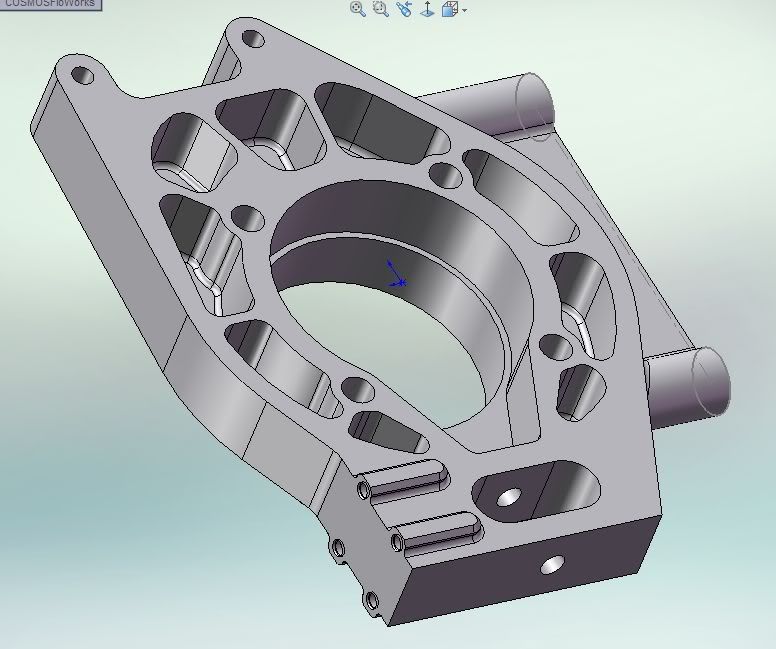
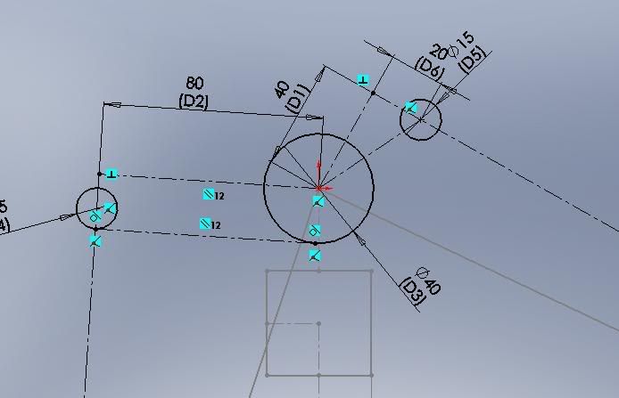
Well here is the sketch of the part in orthographic view.
The largest circle is the centre of the bell crank.. the circle ont he right where the push rod bearing is.
You can see the point to the left "20" on the dotted line of action is where the 90* point is and to the right is the off-set point.

Image


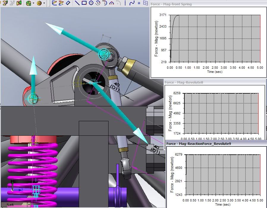
This is the test with it at 90 degrees. A constant force of 4000N is applied to the lower control arm. The the top graph is the force in the spring. THe middle graph is the magnitude of the force in the bell crank bearing. The lowest graph is the force on the push-rod bearing. (The crank has rotated past the initial position).

Image


Next is the test with the 20mm offset. Remember the crank has rotated past the initial position:

Image


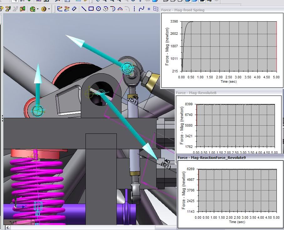
The results are interesting because the 90 degree setup needs a longer push-rod and the offset setup a shorter push-rod for everything to fit. (remember ignore the other parts like the linkage they were not modified for the simulation I just changed the bell crank and push-rod)..

We see that the 90* setup has a smaller force magnitude in the both the spring and the Bell crank bearing. But a higher force in the push-rod.
The offset arm has a higher force in the spring and bell crank bearing but a lower force in the push-rod: ~2 lbs force less. On the other hand more force was put into the spring ~ 40 lbs at the expense of putting more force in the bell crank bearing ~ 40 lbs too. this is reasonable since it is approaching closer to 90.

:-k

I think I should change the behaviour of the force to something else to get better graphs. The input force was also not enough to produce the maximum wheel travel. We need a clearer picture.. but so far it seems the differences are on the order of 10N to 200N with this 4000N force input (900lbs), the differences in imperial are about 2 lbs to 44 lbs difference in the respective parts.. which is very small. Maybe a graph of force compared with the upward movement of the wheel?


But as you can see the space efficiency of the offset bell crank was the major reason why I changed to it. A bigger radius could prevent binding in the 90 degree setup but it just depends on how large the user wants the bellcrank. Maybe a different bell crank radius for the 90 would make it closer but we need to keep things constant for comparison. So radius for radius the offset will have more force in the spring (approaches 90 as it rotates up) but a detriment of more force in the bearing.

**IT is still not clear the shape of the graphs which is more important..whether progressive or not As mep says, i think the 90 one is going to get relatively harder as the suspension moves up. but I want to a graph to compare the progressiveness of each one setup. I will get back with this..

Anyway some other cars use it too.. but this one is a more extreme example.

http://www.ultimatecarpage.com/pic/3824 ... 1b_11.html
πŸ–οΈβœŒοΈβ˜οΈπŸ‘€πŸ‘ŒβœοΈπŸŽπŸ†πŸ™

archebald23
0
Joined: 09 Dec 2009, 09:59

Re: Long Control arms

Post

too much information here, nice to see you guys back your conclusions with visible datas. now what have we accomplished here with regards to long Control Arm?

User avatar
PlatinumZealot
552
Joined: 12 Jun 2008, 03:45

Re: Long Control arms

Post

Doing this little project, I have learned that longer control arms give you finer control of the wheel movement (more space means more available positions/ways for mounting the arms and other components), good camber control, you get more space to route air through the car and you can use a really huge diffuser.

My car has made some progress since I last posted. The progress is mostly in deciding how to approach the calculations for the suspension.

I didn't get a chance to finish testing the bell crank but I will get back to that in due time. I always treat things as a full design not just 3D modeling, that is why it takes me so long.


Looks rudimentary doesn't it?

Image

This view of the front shows the aerodynamic direction I want to take with the car. Full exploitation of the air at the front, using a front diffuser and exhaust ducts. The car will have a formula 1 like nose too. The long control arms also help to accomplish this.

Image
πŸ–οΈβœŒοΈβ˜οΈπŸ‘€πŸ‘ŒβœοΈπŸŽπŸ†πŸ™

marcush.
159
Joined: 09 Mar 2004, 16:55

Re: Long Control arms

Post

exploiting aero to the max in the front design ,wouldnΒ΄t you try and get rid of all
things in between the tyres under the car to avoid convergence of the flow in that area and create a diverging exit duct from this bottleneck ? with a essentially flat floor to the front bulkead you will always not use less than two thirds of available
section width in taht area ...and that is less downforce .
I would think it is entirely possible to put a reasonable step into the flor in front of the engine to create space ,by a more boattype triangulated bottom forming the engine compartment..as you would anyways want a pyramidal shape of the chasis to
create chassis stiffness it will of course lead to lots of awkward angle cuts but i assume you will not fit the tubes with the hacksaw/ file approach but get the bits laser or waterjet cut anyways.

User avatar
PlatinumZealot
552
Joined: 12 Jun 2008, 03:45

Re: Long Control arms

Post

The trapezium shape, I have that in the back of my mind. I just haven't implemented it yet. I just remembered the true reasons why I used a square shaped frame. The square shape was chosen because I want to see how a control arm mounting block that uses shims to change the camber, fits. Those are those hexagonal blocks that you see at the mounts of the control arms. With the square frame you can use nuts and bolts to fasten the control arm mounting blocks (don't have to thread holes), with the trapezium frame you have to use bolts (or stud) and threaded holes because the base piece block will be directly on the frame not on stalks like you see in the the pictures. It is possible to use nut and bolt in the trapezium frame, just have to drill right through the mounting block and then through the frame. I honestly don't know which one is better though; nut and bolt, or bolt and threaded hole, or nut and stud and threaded hole?

The trapezium shape might be on the final car though. I am always open to different ways of doing things until I hit a dead end in a path.

I will think about it some more.

On the body.. I will upload some sketches to show you what I have planned.
πŸ–οΈβœŒοΈβ˜οΈπŸ‘€πŸ‘ŒβœοΈπŸŽπŸ†πŸ™

marcush.
159
Joined: 09 Mar 2004, 16:55

Re: Long Control arms

Post

will the suspension box you have designed not put bendingloads into the upper tubes of the frame leading from the topedge of the frontsuspension box to the A-pillar?
those two ladders are quite long and seem to have not much stiffness laterally.
do you plan to put in a bottom plate or will the engine get a semistressed functionality?

User avatar
PlatinumZealot
552
Joined: 12 Jun 2008, 03:45

Re: Long Control arms

Post

There is to be a Bolted on cross brace that goes on top. It similar to some mid engined cars that have a brace above the engine. I'm not yet certain of how the bottom of the engine bay will be braced. A bottom plate sounds OK.

I'm sorting the front steering now. I made a a major mistake with the front uprights: I made the wheel pivot dead centre over the contact patch. I have a small scrub radius in the lateral direction and zero scrub radius in the longitudinal direction. What I failed to realise is that the caster angle that I put in will have zero effect because of the zero scrub radius in the longitudinal direction. Most websites mostly talk about the scrub and the king pin angle front the front view but not the side view. Marcush, do you know how I determine what is a good scrub radius in the longitudinal direction?
πŸ–οΈβœŒοΈβ˜οΈπŸ‘€πŸ‘ŒβœοΈπŸŽπŸ†πŸ™

marcush.
159
Joined: 09 Mar 2004, 16:55

Re: Long Control arms

Post

n smikle wrote:There is to be a Bolted on cross brace that goes on top. It similar to some mid engined cars that have a brace above the engine. I'm not yet certain of how the bottom of the engine bay will be braced. A bottom plate sounds OK.

I'm sorting the front steering now. I made a a major mistake with the front uprights: I made the wheel pivot dead centre over the contact patch. I have a small scrub radius in the lateral direction and zero scrub radius in the longitudinal direction. What I failed to realise is that the caster angle that I put in will have zero effect because of the zero scrub radius in the longitudinal direction. Most websites mostly talk about the scrub and the king pin angle front the front view but not the side view. Marcush, do you know how I determine what is a good scrub radius in the longitudinal direction?
you are talking of mechanical trail if I understand your post....and with no information about the tyre you will use it seems impossible to quantify.
A typical answer to this would be ,you need some trail to give feel and feedback to the driver and i know JT will kill me for this comment....
to my understanding you start with an assumption on this best of all you look at
cars using the tyres you are going to use with success and at least try to get adjustavility or adaptability to come to this.


So do you plan to have servoassistance to your steering? how much? you could take
caster and trail to extremes but with high downforce and high front weight it may leed to the driver unable to steer the thing precisely.
What is the difference between trail an caster or kingpin inclination,just look how corner weights change for a change with those and ...most important what is your reason to have trail or not and what is the tradeoff compared to caster not using trail.
IΒ΄d say in most cases you will have no chance to get away with zero kingpin inclination ,so this will open the posibility to get scubradius a small as possible.the downside of the kingpin inclination is ,you will experience camber decrease -a move towards positive- with adding steering lock.. so to my understanding it is something you donΒ΄t want to have.

what is with mechanical trail? it is placing your contact patch behind the turning axis or better not centering it and of course this has implications on how the forces are transmitted..to me the advantage of increasing trail is not altering the cornerweights ,but the grip of the tyre will transmit hugely into the steering
so you will need power steering big time taking the trail out of the centre of the contact patch.
Welcome in the variables of suspension layout.. :D

User avatar
PlatinumZealot
552
Joined: 12 Jun 2008, 03:45

Re: Long Control arms

Post

I set the trail at some distance I forgot.

I am at the steering now.

Image

I have been making some observations of ackermann angle. My steering arm is behind the front wheels due to the extra long engine bay. that means I have to have the steering knuckles pointing inwards toward the car. I have not drawn those yet though.

The upright was revised again. This time to allow for proper bolting down of the lower control arm and a mounting for a separate steering knuckle. The steering knuckle is separate only because the intention to machine the upright from a simple block of aluminum.

Here is the incomplete upright.
Image

On the actual roll centre stuff. I don't know where what the hell it's going to land..lol. As you can see the instant centres will lie on the same side of their respective control arms like an F1 car. It wasn't intentional though. I haven't really got around to fine tuning the dimensions yet.. so I hope I can get the Roll centre in a reasonable position.

Image
πŸ–οΈβœŒοΈβ˜οΈπŸ‘€πŸ‘ŒβœοΈπŸŽπŸ†πŸ™

User avatar
mep
29
Joined: 11 Oct 2003, 15:48
Location: Germany

Re: Long Control arms

Post

Ah nice to hear anything new of your project.
On the actual roll centre stuff. I don't know where what the hell it's going to land..lol. As you can see the instant centres will lie on the same side of their respective control arms like an F1 car. It wasn't intentional though. I haven't really got around to fine tuning the dimensions yet.. so I hope I can get the Roll centre in a reasonable position.
Uhhhh,
that’s not what I like to hear but I already expected you didn't spent to much time there.

I just can't understand why you don't care about it. You invest so much time and money into your project but you risk everything when you don't start with a good suspension layout.
It is a simple job to do. Just take some book (name it Vehicle Dynamics by Milken) read a couple of pages there, apply the few basic rules to your suspension and you will get away with a quite well designed layout.
For me this is even one of the most interesting points on a car.

User avatar
PlatinumZealot
552
Joined: 12 Jun 2008, 03:45

Re: Long Control arms

Post

Getting the roll centre is not hard at all so I wasn't too troubled in rushing to find it. The main problems is, I don't know where I want it to be.

People always talk about the roll centre and how to get it, but nobody never ever mentions the ideal location in a quantitative way. When I find I a definitive answer, I will dial in the dimensions for the control arms mounting points. Right now they are sorta in a "safe" layout. I don't mind if you can give me an answer though, I just need something quantitative, even if it just a quantitative objective.
πŸ–οΈβœŒοΈβ˜οΈπŸ‘€πŸ‘ŒβœοΈπŸŽπŸ†πŸ™

User avatar
PlatinumZealot
552
Joined: 12 Jun 2008, 03:45

Re: Long Control arms

Post

So, mep and marcush, the lower the rolling moment the less weight transfer I have, correct? That is the left and right wheel loads are not too disparate. Now, is there such thing as too little weight transfer?

Updates will be coming up. As I said, this is a true mechanical desgin, something that can be built straight off a drawing plot. Like lego. lol
πŸ–οΈβœŒοΈβ˜οΈπŸ‘€πŸ‘ŒβœοΈπŸŽπŸ†πŸ™

User avatar
mep
29
Joined: 11 Oct 2003, 15:48
Location: Germany

Re: Long Control arms

Post

Sorry at the moment I have just very limited access to an internet connection so I hardly find a chance to answer your questions. I will look for some rules of thumb and post them as soon as I get the chance to. At the moment I have to argue some rednecks who think the internet only exists for doing some criminal stuff.

User avatar
mep
29
Joined: 11 Oct 2003, 15:48
Location: Germany

Re: Long Control arms

Post

So, mep and marcush, the lower the rolling moment the less weight transfer I have, correct?
hm I am not totaly sure I think thats wrong. To low roll center could rise your weight transfer due to increased body roll.
Now, is there such thing as too little weight transfer?
Yea generally I don't think there can be something like to little weight transfer but this should be a matter of your tire data. It’s prolly different on your driven axle when you have a high locked differential or even no differential like in a cart. Then you want to unload or even slightly lift your inside wheel to let it spin free.


Regarding roll center location:
Lower RC is reducing weight transfer but the distance between RC and center of gravity is rising This results in higher body roll. Higher body roll will be counteracted by your springs or anti roll bar which should result in weight transfer again. That’s why I think you don't want your RC to low but you must have more things in mind. Achieving a high roll center is not so easy and brings you other negative effects like jacking and increased track gain during bump. That is caused by the higher instant center location which you need to achieve your high RC. All these suspension components are somehow related to each other.
Maybe best thing you can do is take some time and make some basic calculations starting with center of gravity high and expected cornering forces.

marcush.
159
Joined: 09 Mar 2004, 16:55

Re: Long Control arms

Post

low centre of gravity will help to keep the distance of roll centre and cg height low ,so you can achieve the desired geometries.
hopefully you are able to build your car underweight so a low CofG is easier to achieve.