Oil Tank Design - seeking photos or discussion

All that has to do with the power train, gearbox, clutch, fuels and lubricants, etc. Generally the mechanical side of Formula One.
stolenmojo
0
Joined: 23 Apr 2008, 14:22
Location: USA

Oil Tank Design - seeking photos or discussion

Post

I was curious as to the design of F1 oil tanks for the dry sump systems, which seem to me to be similar to sports car systems as well. I can't seem to find any information quickly on the web though. I managed to turn up a mysterious photobucket pic of a honda oil tank sectioned which showed a nice oil pickup inside a carbon tank but otherwise haven't seen much.

Mainly I am interested in the following:
how is deaeration handled on the return flow?
how is the sump area designed to offset vehicle g loading to provide high quality oil under all accel conditions?
is the oil tank pressurized to achieve the sump operating conditions?
how much oil is consumed by the engine during a race event?

anybody got any insight?

Thanks,
Brandon

stolenmojo
0
Joined: 23 Apr 2008, 14:22
Location: USA

Re: Oil Tank Design - seeking photos or discussion

Post

I "borrowed" this image from Concept Racing UK: http://www.conceptracing.co.uk/cosworth-oil-tank/

Some interesting fab projects on their site if you look around further.

Image

It seems the deaeration chamber is located on the bottom of the tank behind the wiggins on the return, but I don't understand if oil is pumped up to the secondary deaeration assembly and then runs back down that feed tube to the tank outlet or back down to the sump area at the base of the tank.

simieski
9
Joined: 29 Jul 2011, 18:45

Re: Oil Tank Design - seeking photos or discussion

Post

I have nothing F1 specific but I can provide you with a couple of diagrams of how the Boeing 737 achieves deaeration of engine oil if it would be of any use to you.
Thank you to God for making me an Atheist - Ricky Gervais.

riff_raff
132
Joined: 24 Dec 2004, 10:18

Re: Oil Tank Design - seeking photos or discussion

Post

stolenmojo,

The deaeration of engine oil is usually performed by a centrifugal mechanical separator built into the scavenge pump assembly. Removing air bubbles from the engine oil is critical for journal bearing life.

The picture you posted is typical for F1 oil tanks. They are tall and skinny to minimize oil sloshing due to lateral acceleration forces. Due to the relatively high turnover rates in the engine oil volume, some sort of additional tank baffles are also helpful at reducing aeration at the pressure pump pick-up.

Some of those tubes and baffles may also be part of the air return circuit from the separator. This airflow volume can be quite significant in a dry-sumped high rpm engine. And since that scavenge airflow contains some amount of oil, it can't be discharged overboard.

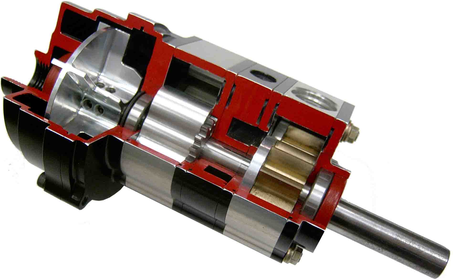
Here's a picture of a scavenge pump with a deaerator impellor:

Image
"Q: How do you make a small fortune in racing?
A: Start with a large one!"

stolenmojo
0
Joined: 23 Apr 2008, 14:22
Location: USA

Re: Oil Tank Design - seeking photos or discussion

Post

simieski wrote:I have nothing F1 specific but I can provide you with a couple of diagrams of how the Boeing 737 achieves deaeration of engine oil if it would be of any use to you.
Yeah I'd love to see it, never hurts to learn something new.

Thanks,
Brandon

stolenmojo
0
Joined: 23 Apr 2008, 14:22
Location: USA

Re: Oil Tank Design - seeking photos or discussion

Post

[quote="riff_raff"]stolenmojo,

The deaeration of engine oil is usually performed by a centrifugal mechanical separator built into the scavenge pump assembly. Removing air bubbles from the engine oil is critical for journal bearing life.

The picture you posted is typical for F1 oil tanks. They are tall and skinny to minimize oil sloshing due to lateral acceleration forces. Due to the relatively high turnover rates in the engine oil volume, some sort of additional tank baffles are also helpful at reducing aeration at the pressure pump pick-up.

Some of those tubes and baffles may also be part of the air return circuit from the separator. This airflow volume can be quite significant in a dry-sumped high rpm engine. And since that scavenge airflow contains some amount of oil, it can't be discharged overboard.

Here's a picture of a scavenge pump with a deaerator impellor:

end quote]

The impellor is an interesting tidbit, so does that mean there are multiple return lines to the oil tank? once the oil and air are separated is air bled off of the rear stage back to the tank? is your pic only a scavenge pump?

I'm familiar with multi stage scavenge but have never seen the separator impellor detail.

Seems the return deaeration chamber would be small in diameter to keep the oil attached on the walls all the way around regardless of lateral accel. But what happens when the vehicle has relatively high vertical accels too? Maybe this is where the 737 deaeration info would be handy.

riff_raff
132
Joined: 24 Dec 2004, 10:18

Re: Oil Tank Design - seeking photos or discussion

Post

stolenmojo,

The picture of the separator impellor is not for an F1 engine scav pump, but it does show the basic configuration. And yes, there are separate returns for the air and oil. If you look closely at the impellor, you'll see some holes near the center between the blades, and you can also see the air discharge port on the shaft centerline just to the left of the impellor. This is where the air exits. The impellor works by the difference in density between the air and oil. With an F1 scav pump, the volume flow of air would be much greater than oil, so the impellor design would be different.

As for aircraft engine oil systems, they typically use something called a "Lubriclone" for the primary separation: http://www.tedecoindustrial.com/diag.htm

And for removing any residual oil from the air dumped overboard, a high-speed separator is used.

riff_raff
"Q: How do you make a small fortune in racing?
A: Start with a large one!"

simieski
9
Joined: 29 Jul 2011, 18:45

Re: Oil Tank Design - seeking photos or discussion

Post

stolenmojo wrote:
simieski wrote:I have nothing F1 specific but I can provide you with a couple of diagrams of how the Boeing 737 achieves deaeration of engine oil if it would be of any use to you.
Yeah I'd love to see it, never hurts to learn something new.

Thanks,
Brandon
The first image just shows a cutaway of the oil tank, a baffle assembly is used to limit the oil movement in the tank under g loading.

Second picture is a more detailed illustration of the air/oil seperator. 3 scavenge pumps provide return oil to the tank from the fwd sump, aft sump and accessory gearbox. After going through the swirl chamber air vents up through the centre hollow shaft to the forward bearing package oil sump.

Let me know if any other information about the system would be of use.

Image

Image
Thank you to God for making me an Atheist - Ricky Gervais.

Edis
59
Joined: 31 Jan 2010, 16:58

Re: Oil Tank Design - seeking photos or discussion

Post

The main advantage of the centrifugal separator is that the oil tank can be made much smaller since most of the air/oil separation is made by the separator. From the separator there are two outputs, oil (also contains some air) and air (also contains some oil) and both are returned to the tank. The air return is generally returned to a higher, different position in the tank. In F1 the air from the dry sump system is returned to the engine airbox.

There are some good pictures of the tank, separator and dry sump pump of a Cosworth F1 (CR3L) engine at Gurneyflap. Do however note that this engine uses external lobe (roots) type scavenge pumps which is quite uncommon for a F1 engine these days, most F1 engines use gerotor pumps for the scavenge stages built into the lower crankcase (typically five or six stages for a V8).

http://www.gurneyflap.com/engine.html

riff_raff
132
Joined: 24 Dec 2004, 10:18

Re: Oil Tank Design - seeking photos or discussion

Post

simieski,

Thanks for posting the diagrams of the air/oil separator on the 737.

I actually worked on the EMAD gearbox design on the Roll-Royce BR715 engine, which was used on the Boeing 717. On that engine, all engine oil flow drained through the EMAD which was mounted below the LP compressor case. There was also a large quantity of airflow from the engine bearing chambers, due to labyrinth seal leakage in the compressor/turbine stages, that passed into the EMAD housing along with the engine oil.

The EMAD was dry-sumped and the scavenged oil passed thru a "Lubriclone" deaerator before being discharged into the EMAD oil reservoir. The airflow discharged from the Lubriclone then passed thru a secondary high speed centrifugal mechanical separator, and finally thru a fine porous sintered stainless steel filter. It was necessary to remove every last trace of oil from the air being discharged overboard, due to emissions regulations.

riff_raff
"Q: How do you make a small fortune in racing?
A: Start with a large one!"

User avatar
ringo
227
Joined: 29 Mar 2009, 10:57

Re: Oil Tank Design - seeking photos or discussion

Post

Edis wrote:The main advantage of the centrifugal separator is that the oil tank can be made much smaller since most of the air/oil separation is made by the separator. From the separator there are two outputs, oil (also contains some air) and air (also contains some oil) and both are returned to the tank. The air return is generally returned to a higher, different position in the tank. In F1 the air from the dry sump system is returned to the engine airbox.

There are some good pictures of the tank, separator and dry sump pump of a Cosworth F1 (CR3L) engine at Gurneyflap. Do however note that this engine uses external lobe (roots) type scavenge pumps which is quite uncommon for a F1 engine these days, most F1 engines use gerotor pumps for the scavenge stages built into the lower crankcase (typically five or six stages for a V8).

http://www.gurneyflap.com/engine.html
And do you have examples of the gerotor pumps?
For Sure!!

User avatar
ringo
227
Joined: 29 Mar 2009, 10:57

Re: Oil Tank Design - seeking photos or discussion

Post

riff_raff wrote:simieski,

Thanks for posting the diagrams of the air/oil separator on the 737.

I actually worked on the EMAD gearbox design on the Roll-Royce BR715 engine, which was used on the Boeing 717. On that engine, all engine oil flow drained through the EMAD which was mounted below the LP compressor case. There was also a large quantity of airflow from the engine bearing chambers, due to labyrinth seal leakage in the compressor/turbine stages, that passed into the EMAD housing along with the engine oil.

The EMAD was dry-sumped and the scavenged oil passed thru a "Lubriclone" deaerator before being discharged into the EMAD oil reservoir. The airflow discharged from the Lubriclone then passed thru a secondary high speed centrifugal mechanical separator, and finally thru a fine porous sintered stainless steel filter. It was necessary to remove every last trace of oil from the air being discharged overboard, due to emissions regulations.

riff_raff
why wasn't this air sent to the turbine stage?
For Sure!!

User avatar
flynfrog
Moderator
Joined: 23 Mar 2006, 22:31

Re: Oil Tank Design - seeking photos or discussion

Post

ringo wrote:
Edis wrote:The main advantage of the centrifugal separator is that the oil tank can be made much smaller since most of the air/oil separation is made by the separator. From the separator there are two outputs, oil (also contains some air) and air (also contains some oil) and both are returned to the tank. The air return is generally returned to a higher, different position in the tank. In F1 the air from the dry sump system is returned to the engine airbox.

There are some good pictures of the tank, separator and dry sump pump of a Cosworth F1 (CR3L) engine at Gurneyflap. Do however note that this engine uses external lobe (roots) type scavenge pumps which is quite uncommon for a F1 engine these days, most F1 engines use gerotor pumps for the scavenge stages built into the lower crankcase (typically five or six stages for a V8).

http://www.gurneyflap.com/engine.html
And do you have examples of the gerotor pumps?
the one located in my truck

Image

User avatar
flynfrog
Moderator
Joined: 23 Mar 2006, 22:31

Re: Oil Tank Design - seeking photos or discussion

Post

ringo wrote:
riff_raff wrote:simieski,

Thanks for posting the diagrams of the air/oil separator on the 737.

I actually worked on the EMAD gearbox design on the Roll-Royce BR715 engine, which was used on the Boeing 717. On that engine, all engine oil flow drained through the EMAD which was mounted below the LP compressor case. There was also a large quantity of airflow from the engine bearing chambers, due to labyrinth seal leakage in the compressor/turbine stages, that passed into the EMAD housing along with the engine oil.

The EMAD was dry-sumped and the scavenged oil passed thru a "Lubriclone" deaerator before being discharged into the EMAD oil reservoir. The airflow discharged from the Lubriclone then passed thru a secondary high speed centrifugal mechanical separator, and finally thru a fine porous sintered stainless steel filter. It was necessary to remove every last trace of oil from the air being discharged overboard, due to emissions regulations.

riff_raff
why wasn't this air sent to the turbine stage?
a couple of reason off the top of my head the air pressure is much to high in the turbine stage. I am assuming you are talking about the compressor stage and not the recovery stage in that it may not burn clean enough and coke up the diffuser in the burner.

User avatar
ringo
227
Joined: 29 Mar 2009, 10:57

Re: Oil Tank Design - seeking photos or discussion

Post

The turbine works at the same pressure as the compressor.
And it reduces after that. Turbine engines are constant pressure combustion engines, so i was wondering why this air being dirty and all, wasn't simply fed back to the turbines.
For Sure!!