This archaic Brit 2T unit - interestingly - utilizes a crank flywheel - as a 3D rotary valve..
http://www.villiers.info/Alpha/index.htm
- Login or Register
No account yet? Sign up
manolis wrote: ↑28 Apr 2017, 09:39Hello J.A.W.
You write:
“This archaic Brit 2T unit - interestingly - utilizes a crank flywheel - as a 3D rotary valve..
http://www.villiers.info/Alpha/index.htm”
Nice link and story.
The crankshaft with the “disk / cylindrical /drum” valve of the two-cylinder Alpha 250cc Centuri, is shown, but not too clearly. I suppose it is made of two independent crankshafts secured on the “disk” valve at the centre.
Thanks
Manolis Pattakos
Is this:

Ta for that P & T-C, & here is an example of a 'twingle' ( 360`crank/twin-fire 2T);Pinger wrote: ↑28 Apr 2017, 12:58Is this:
''As the disc controlled inlet periods of less than 180 degrees, this system was deemed as perfectly satisfactory for the state of tune prevailing some thirty years ago. With modern high performance engines having an inlet period of truly wild proportions, this system would not be adequate, and a change to twin carburetors would have been required.''
not the clue to 180 degree crank?
edit PS.
Carb size also. A 29mm Dell Orto which was downsized by only 1mm for the single cylinder 125.
You are correct - that was for a petrol engine. Unfortunately there is not a similar chapter for diesels. Surely the principles I have mentioned must be the same though ?
Which is a key benefit of the cross-head design.
1. Elimination of tilting of the piston improves efficiency of all the rings allowing reduced ring tension and reduced lubrication.
Not exactly. Piston secondary motion has little effect on ring performance. For all practical purposes the rings can be assumed to only react piston forces along the bore centreline. The circumferential gradient of ring pressure is also assumed to be 0. In Manolis' design there will still be a small amount of radial motion due to the clearances in the sliders - maybe it is a bit smaller than for a conventional piston but realistically it will not have a measurable effect.
As for reducing ring tension - do not forget that the main purpose of the rings is to seal the combustion pressure. Tension is there to prevent radial collapse. Maybe the oil ring spring load can be reduced a bit but I am not convinced. At the end of the day you still have 2x sliders, 3x big end bearings and 2 sets of rings where 1 piston with 1 small end and 1 big end would have sufficed. I choose to completely ignore arguments of the type 'X has thrown 100 millions at it and made it work'. Where I work we design very successful racing engines for just over a tenth of that. With that much money you should be able to fly a lawn mower engine to the moon.
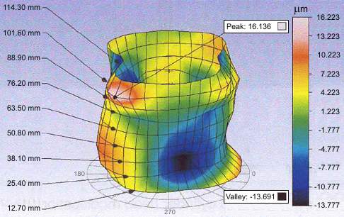
Anyway, back to piston rings: One of the big disadvantages of liner ports is the high amplitude high order distortion of the bore. The shape filling capacity of the ring is inversely proportional with the 4th power of the order of distortion. In a conventional engine, the dominant distortion order is more or less the number of head bolts and its amplitude is quite low. In a liner full of 'holes' the order will be much higher and the amplitudes larger - that is to say they will be rubbish at sealing. I am trying to keep this post reasonably short - if you want any further details on the physics/ maths I will be more than happy to share.
2. Eliminating the skirt as a cross-head bearing further reduces the quantity of oil required on the bore.
Again, not too sure about this.. oil will still be required to lubricate the rings and I assume a fair bit will also be used to cool the pistons. And as I have mentioned before there's the issue of oil pooling in the upside down piston.
A cylinder head that leaks oil, yes.I am sure this is not a deliberate attempt to mislead and you simply overlooked the fact that the extra piston contributes its own displacement, so oil consumption as a function of engine displacement remains the same were you to substitute the opposing piston with a cylinder head.
I re-read this several times and it did not make sense once. I'll give you the benefit of the doubt and put it down to the language barrier.A pulling connecting rod is way stronger for the loads it bears (so it can substantially more lightweight) than a conventional connecting rod. The heavy loads in the OPRE / PatOP try to strengthen the connecting rods.
That's not what I said. I said the losses are about the same. You said there are no losses at all which is plainly wrong.So, the cross-head design and the hydrodynamic lubrication increase the frictional loss!
While I agree that journal bearings can be optimized to achieve similar power losses to roller bearings - this can only be done reliably for steady-state operation. When a journal bearing operates very close to the mixed lubrication boundary it is very unstable thermally, meaning a momentarily increase in friction can cascade into an increase in temperature which lowers the viscosity, which in turn increases friction even more, etc - resulting in rapid failure.The hydrodynamically lubricated plain bearings have a coefficient of friction similar to the coefficient of friction of the cylindrical roller bearings (in the range of 0.001).
With hydrodynamic lubrication the coefficient of friction of the cross-head is similar.
The lubricant is provided under pressure between the flat slides (or slippers) and the flat slideways of the cross head.
It is a forced lubrication (not the “splash” lubrication of the conventional “trunk piston” engines wherein, among others, the cylinder liner undergoes significant deformation).
And it has to do with flat surfaces that perfectly fit with each other.
Cheapo 2T utility engines such as domestic lawn-mowers commonly featured plain big-ends..Pinger wrote: ↑29 Apr 2017, 09:14Re plain vs roller bearings. The losses accrued from pumping the oil to plain bearings cannot easily be overlooked. If there was no benefit from roller bearings, then doubtful if OEM would be adopting them for camshafts etc. I think Porsche recently patented a built up crank assembly method to enable roller bearings to be used. Also - though happy to be proved wrong - I cannot recall an engine started only by kick (or pull) starter ever having plain bearings (other than splash lubed side valve donkey engines).
