Wing aero

Here are our CFD links and discussions about aerodynamics, suspension, driver safety and tyres. Please stick to F1 on this forum.
Tommy Cookers
616
Joined: 17 Feb 2012, 16:55

Re: Wing aero

Post

flyboy2160 wrote:
Tommy Cookers wrote:presumably he was not speaking (in aviation) of tip vortices ?
It was many years ago, so my memory isn't exact, but I think he was creating a mid-wing vortex with a leading edge snag to stabilize the airflow departure on the outer wing panel.
the leading edge snag as in your A-7 picture (UK term was sawtooth, very popular in 50s planes)

my book says this is to prevent (in some transonic flight conditions) the inwards migration of tip vortices
that would otherwise disrupt the attached flow at the rear of the inner part of the wing
and cause catastrophic 'pitch-up'
(there was lots of this in those days eg F-100, sometimes we Brits had fences and sawteeth on the same plane eg Scimitar)

IIIRC the first creation of a 'mid-wing' vortex to stabilise lift flow was the Saab Draken ('double-delta', a giant LEX ?)
(someone told me that they didn't know the CoP location properly, so they made space to move the engine by metres for CG
which is why it had an afterburner the size of Texas)

flyboy2160
84
Joined: 25 Apr 2011, 17:05

Re: Wing aero

Post

shelly wrote:@timbo, flyboy - in the ferrari picture what i was pointing at (calling it snag for lack of a better word) is the change of section in the pylons above the "ferrari world" tag
shelly, do we need the flow at some horizontal AOA to that edge to trip the vortex? does this come about by angling the pylons/nose extensions a little to the straight ahead flow direction?

flyboy2160
84
Joined: 25 Apr 2011, 17:05

Re: Wing aero

Post

Tommy Cookers wrote:....
which will themselves shed vortices at high AoA, preventing weapon aiming (as in the F-4)
unless designed as a chisel nose with related LEXs as in the (trendsetting) F-5
fins/vertical stabilisers seem from the 30s to have often used the 'LEX/LERX' configuration, for higher useable AoA
yes. my memory is that the F5 LEX was discovered by the tunnel guys playing around and it did give improved high AOA performance. it was carried over to the YF17/F18. those planes had twin canted verticals instead of the single central vertical on the F5, and the LEX vortices initially were in the perfect place to excite the twin verticals to very high Gs! There was a lot of messing around/brute force strengthening to overcome this excitation. vortices can be your friend, but when they are your enemy, they can be very powerful.

shelly
136
Joined: 05 May 2009, 12:18

Re: Wing aero

Post

I boorow a picutre from autosport (posted by Crucial Xtreme in the f138 thread today) that shows that the pylons are angled to the simmetry plane of the car.
Image
I am not sure if the pressure is higher in the inner channel btw the pylons than outside them - I would tend to think tha opposite, i.e. lower pressure in the channel. This inflences the side of the pylon where the vortex develops
twitter: @armchair_aero

flyboy2160
84
Joined: 25 Apr 2011, 17:05

Re: Wing aero

Post

shelly wrote:I boorow a picutre from autosport ....
Thanks for your insights!

Crucial_Xtreme
404
Joined: 16 Oct 2011, 00:13
Location: Charlotte

Re: Wing aero

Post

shelly wrote:@timbo, flyboy - in the ferrari picture what i was pointing at (calling it snag for lack of a better word) is the change of section in the pylons above the "ferrari world" tag
Shelly are you referring to the "snag point" being at the yellow arrows? If so we can get a glimpse as to how it's affecting flow.

Image

shelly wrote:I boorow a picutre from autosport (posted by Crucial Xtreme in the f138 thread today) that shows that the pylons are angled to the simmetry plane of the car.

I am not sure if the pressure is higher in the inner channel btw the pylons than outside them - I would tend to think tha opposite, i.e. lower pressure in the channel. This inflences the side of the pylon where the vortex develops
Being that the pylons are severely angled inwards like Venturi the pressure should be decreased no?

Here we can see how pylons form Venturi
Image


Sorry I know this isn't necessarily "front wing aero" but it's in response to post already made in the thread. :)

flyboy2160
84
Joined: 25 Apr 2011, 17:05

Re: Wing aero

Post

Crucial_Xtreme wrote:..Shelly are you referring to the "snag point" being at the yellow arrows? If so we can get a glimpse as to how it's affecting flow...
I don't mean to speak for shelly, since he started this observation, but I thought we were talking about the kink just above and forward of the "F" in "Ferrari WORLD." About at 10 o'clock from the "F."
Last edited by flyboy2160 on 26 Apr 2013, 21:41, edited 1 time in total.

shelly
136
Joined: 05 May 2009, 12:18

Re: Wing aero

Post

Yes I meant what flybooy has said: the kink on the leading edge of the pylon.
The pylons are angled to form a duct that gest narrower from the leading edge going to the back, but I would not call it a venturi. The situation is different from having incompressible fluid constrained in a pipe - in external aero the fluid can go both inside and outside the channel formed by the pylons, and the mass flow through the channel depends on the flow fied conditions outside it.
So I think that the reasoning: the pylons are converging->it's a venturi-> there must be low pressure inside them is wrong. But I agree on the fact that probably there is low pressure between the pylons:
1) there is low pressure between the front turning vanes behind the pylons, that drives flow through the channel between them (I think that ferrari tunes that pressure with different sizes of the shark mouth, but that's another topic)
2) in short channels there is a contribution to low pressure due to the acceleration around the leading edges
3) low pressure between the pylons would be beneficila to have vortices detaching form their lower edges at y=250 rotating in the correct sense to contribute to the t-tray vortices, like the now banned turning vanes Pierc cited
4) there seem to be no evidence of vortex on the flow vis crucial posted above - so its either of two: or pressure is lower in the channel, so the vortices roll on the inside fo the pylons, or there is no vortex detachment from the kink
twitter: @armchair_aero

flyboy2160
84
Joined: 25 Apr 2011, 17:05

Re: Wing aero

Post

shelly wrote:...... so the vortices roll on the inside fo the pylons, or there is no vortex detachment from the kink
yes. I also can see it either way: vortex or not. with a horizontal AOA due to the knock-kneed pylon orientation, you theoretically would see a vortex at that snag. but if you really wanted to trip it, why not make the kink as a sharp crease instead of as the generous fillet they show? (I'm a composites guy: the sharp crease would be ok structurally.) to make it work more consistently in yaw?

I find it hard to believe they need the wider/thicker section above the kink for structural reasons.

shelly
136
Joined: 05 May 2009, 12:18

Re: Wing aero

Post

Image

I have put some crude lines on the above picture to sketch the two endplate vortices.
The outer vortex in green runs below the arched shape of the footplate, helixing in the sense of the green arrow.
From china ferrari has a unique solution in this zone, because the footplate has two slots that feed the vortex - multiple feeding leading edges give a better vortex (see also for example lotus' slotted bargeboard). So the air coming from top of the footplate passes in the two slots, gets accelerated under the slot leading edge, and roll together with the vortex that strats at the corner of the endplate.

The yellow vortex forms on the inside of the endplate (or inside the arch of endplate-less designs). It provides a strong low pressure in that zone, and is fed by the multiple slots on the top and on the side, between the 6 elements of the wing. So the slots have the double function of energising the flow in the multilelement arrangement, and energising the yellow vortex.

These two vortices, with all the others developed in this zone (like the one generated by the air spill over from the top of the front wing, that rolls around the black triangle element at top right in the picture), interact downstream with the front wheel. It could be that the low pressure of the vortices has an effect in reducing drag in front of the wing, like the small ari dams on most production cars
twitter: @armchair_aero

shelly
136
Joined: 05 May 2009, 12:18

Re: Wing aero

Post

From the Catheram Ct03 thread:
R_Redding wrote:It started at 22mins

Image
http://www.youtube.com/watch?v=LD-HTFGZ ... e=youtu.be
on the video you can see the vortex swirling around .... I'm not too sure what this indicates

Is it correct...are they doing it deliberately?...

Rob
Finally visible - the bargeboard vortex running under the floor
twitter: @armchair_aero

shelly
136
Joined: 05 May 2009, 12:18

Re: Wing aero

Post

Image

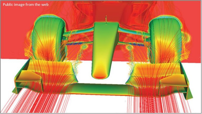
f1-like front wing cfd image, from de Luca article on gocar.gr (http://www.gocar.gr/races/f1/10001,Unse ... tyres.html)

I hope to find the first source of this "public image from the web" - it could be some ferrari document for journalists, or from a specialized magazine like RCE or Bernoulli.

The set-up shown here is basic / outdated (it has 2008 tyres it seems), but still rich of information. It seems a simplifide model without pillars (in the sens that they are not just not shown, you see no sign of them in terms fo flow interaction on the top part of the central wing profile,

I think what we are seeing here in terms of colors is:
-pressure coefficient on the car body
-total pressure on the cutaway plane
-streamlines coloured by total pressure

The picture shows a lot of facts. We see two vortices detach from the flap -inner and outer; we seem the streamlines tune from red to green - blue in the vortices as static pressure goes down and you have some losses.

We do not see other vortices because the streamlines shown do not pass through the relavant zones (e.g. endplate edge).

Flow fon the lower front wishbone: see the change in color (pressure) on it on the inside and outside of the vortex becuse of the different AoA (upwash form the wing and transition up to down across the vortex).

On the inboard edge of the flap: small low pressure zone induced by the tip vortex

Flow on the flap that goes inside/outside the front wheel: the first stremline passing on the inside is much more inboard that one would expect - flow on the flaps is mostly oblique as it is demonstrated on corrent pit lane pictures by the orientation of flap arch supports and incidence adjusters

On top of the front wheel: total pressure loss in blue

On the lowest point of the cutaway plane the blue tyre wake is a bit larger: tyre squirt

Stagnation on the upper surface of the nose - not on its leading edge. The shepe of the stagnation gives an hint about how 3dimensional the fow on the nose is

High pressure on the tyre front face but also low pressure on the side shoulder - shoulder shape crucial for lateral flow between tyre and endplate
twitter: @armchair_aero

stez90
8
Joined: 10 Jul 2012, 23:31

Re: Wing aero

Post

maybe they are useful

Image

and http://youtu.be/pREgFVRXeDI (last half of the video)

User avatar
FW17
165
Joined: 06 Jan 2010, 10:56

Re: Wing aero

Post

Surface Texture Through Buckling

Generating a surface texture in a shell can improve how the shell or structure interacts with the world around it. In the example below, a simple model of an airfoil section has a thin membrane wrapped around a solid core. The membrane is marginally wider than the core, and the wooden endplates can be moved axially in a controlled manner by turning the nuts. In one state, the surface is completely smooth; in the other, the endplates are compressing the membrane, which has clearly buckled. However, the core restricts both local buckling and the out-of-plane movement to such a degree that a regular buckle/wrinkle pattern forms over the entirety of the surface: notice how the size of the buckle facets are proportional to the radius of curvature of the section. Present testing of similar specimens in a wind tunnel indicates that switching on the texture, at the correct windspeed, can reduce the drag signficantly - as the dimples do on a golfball. But unlike a golfball, the surface can be switched to smooth again in order to yield better aerodyanmics at a different speeds. Other potential applications include "haptic" electronic displays, where the user experiences a tactile feedback, and building facades with tuneable reflection and absorption characteristics.

ImageImage
A simple wing structure that can be smooth or textured, depending on the compression of the end plates

© 2013 Advanced Structures Group

User avatar
godlameroso
309
Joined: 16 Jan 2010, 21:27
Location: Miami FL

Re: Wing aero

Post

You could do it to the rear wing if mastered the art of deformable endplates. On another note, does anyone think that Williams switch to a matte paint has any influence on drag?
Saishū kōnā