Downforce calculation Equation

Here are our CFD links and discussions about aerodynamics, suspension, driver safety and tyres. Please stick to F1 on this forum.
al_garnett
0
Joined: 31 Oct 2014, 16:06

Downforce calculation Equation

Post

Hey guys,
The following formula is provided on the wikipedia page for downforce,

D=0.5(WS)*H*alpha*F*rho*V^2
Where:

D is downforce in newtons
WS is wingspan in metres
H is height in metres
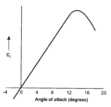
\alpha is angle of attack
F is lift coefficient
rho, ρ, is air density in kg/m³
V is velocity in m/s

Does anybody know the source of this Formula or how its is derived? I need to reference/cite it for a university project but can't find it anywhere. We are not able to reference wikipedia articles.

Thanks

Greg Locock
233
Joined: 30 Jun 2012, 00:48

Re: Downforce calculation Equation

Post

I suspect it is fanboi rubbish

NoDivergence
50
Joined: 02 Feb 2011, 01:52

Re: Downforce calculation Equation

Post

This is called the lift equation, maybe sometimes referred to as the lift formula. Only thing I don't agree with is the alpha.

L = 1/2 rho V^2 S C_L

where S is the planform area, and rho, the density of the flow

Downforce is the same as lift except the sign for C_L will simply be negative.

Cold Fussion
93
Joined: 19 Dec 2010, 04:51

Re: Downforce calculation Equation

Post

That is a very strange way or writing the lift formula and I wouldn't say is correct. The lift coefficient depends on many things, one of them is angle of attack and height above the ground, so why is then in main lift formula? In any case that formula wont give you a force at the end of it. You should use the formula that NoDivergence posted.

al_garnett
0
Joined: 31 Oct 2014, 16:06

Re: Downforce calculation Equation

Post

NoDivergence wrote:This is called the lift equation, maybe sometimes referred to as the lift formula. Only thing I don't agree with is the alpha.

L = 1/2 rho V^2 S C_L

where S is the planform area, and rho, the density of the flow

Downforce is the same as lift except the sign for C_L will simply be negative.
However a wing runs in ground effect which raises downforce generated. If the formula is used, finding the lift coefficient from a cfd experiment, without the wing in ground effect, and the result compared to a cfd simulation where the wing is modelled with the road below. The results are close enough to be called the same.this seems to suggest the formula does work.

Greg Locock
233
Joined: 30 Jun 2012, 00:48

Re: Downforce calculation Equation

Post

seriously, when the formula claims WS=wingspan? So the geometrical scaling dimension is wingspan * height(presumably off the ground)?

I doubt alpha has any directly linear relationship with THAT.
Last edited by Greg Locock on 20 Mar 2015, 12:26, edited 1 time in total.

CBeck113
51
Joined: 17 Feb 2013, 19:43

Re: Downforce calculation Equation

Post

>>Edit: Greg was right, and this was sh*t<<

Here is a link for a better explanation of the lift equation:
http://www.ppl-flight-training.com/lift-formula.html
Last edited by CBeck113 on 20 Mar 2015, 15:15, edited 1 time in total.
“Strange women lying in ponds distributing swords is no basis for a system of government. Supreme executive power derives from a mandate from the masses, not from some farcical aquatic ceremony!” Monty Python and the Holy Grail

Greg Locock
233
Joined: 30 Jun 2012, 00:48

Re: Downforce calculation Equation

Post

um, no, it just looks a bit like that

Cold Fussion
93
Joined: 19 Dec 2010, 04:51

Re: Downforce calculation Equation

Post

al_garnett wrote:
NoDivergence wrote:This is called the lift equation, maybe sometimes referred to as the lift formula. Only thing I don't agree with is the alpha.

L = 1/2 rho V^2 S C_L

where S is the planform area, and rho, the density of the flow

Downforce is the same as lift except the sign for C_L will simply be negative.
However a wing runs in ground effect which raises downforce generated. If the formula is used, finding the lift coefficient from a cfd experiment, without the wing in ground effect, and the result compared to a cfd simulation where the wing is modelled with the road below. The results are close enough to be called the same.this seems to suggest the formula does work.
That's not how that formula will work though. That will give you increasing downforce with increasing height, which doesn't make any conceptual sense. The proper way to evaluate this is group it all into the coefficient of lift.

User avatar
Tim.Wright
330
Joined: 13 Feb 2009, 06:29

Re: Downforce calculation Equation

Post

Looks like they are using the basic lift formula but replacing the frontal area with WS x H which for a rectangular section is the frontal area. I also don't understand the alpha though. I think its an error.

The whole article seems a bit crap which is often the case when automotive engineers try to reinvent the explanation of certain physical effects rather than using good old classical mechanics.

On that note, if you insist on using wikipedia - at least use the more general page for "aerodynamic lift":
http://en.wikipedia.org/wiki/Lift_%28force%29
Not the engineer at Force India

Blanchimont
214
Joined: 09 Nov 2012, 23:47

Re: Downforce calculation Equation

Post

If F is the slope (Cl/AoA) in the linear range in a plot like this

Image

then the formula can be used in the linear range for a symmetrical foil. I would replace WS*H with the wing surface seen from above.

D=0.5(WS)*H*alpha*F*rho*V^2
[D] = [m*m*rad*1/rad*kg/m³*m²/s²] = [m*kg/s²] = [N]
Dear FIA, if you read this, please pm me for a redesign of the Technical Regulations to avoid finger nose shapes for 2016! :-)

Greg Locock
233
Joined: 30 Jun 2012, 00:48

Re: Downforce calculation Equation

Post

So how different would that curve be for a multielement heavily cambered short wing with end plates, operating at or beyond the stall point, in a highly variable flow?

NoDivergence
50
Joined: 02 Feb 2011, 01:52

Re: Downforce calculation Equation

Post

Completely and totally would depend on the flow and geometry and location of the main element and flap/slats.

I would guestimate that Cl_alpha would be above, but somewhat near 2pi/radian (likely around 7/radian for a conventional slat/main/flap airfoil) in the linear region, but past that, trust me, who the hell knows.

Using alpha in the lift equation makes absolutely.

panayiotis
0
Joined: 25 Apr 2015, 19:07

Re: wheel base

Post

can anyone knows where i can find the wheelbase, rear and front track. also the weight distribution. only for 2014 f1 cars...thnx in advance

SpainFAN
0
Joined: 21 May 2014, 10:26

Re: Downforce calculation Equation

Post

AoA is fix as is the wing, unless you are varying the AoA, that's why C_l is used. An airfoil, and therefore a will will have a CL envelop with C_lmin-C_lmax at each extreme.

A multielement wing is just that, a multi-element wing, which would a its own C_l at a given AoA for a given airfoil.

Multi-Element is BTW the best way to gain higher C_l in a given wing. Most aviation application is useless because of limits in build technology to get wing span load distribution. there was a glider that had very short wing span, utilizing multi element wing at the tips.

Endplates are a highly debated subject by aeodynamicist...