Front Wing Assembly

Here are our CFD links and discussions about aerodynamics, suspension, driver safety and tyres. Please stick to F1 on this forum.
argi2007
1
Joined: 26 Jul 2009, 23:45

Front Wing Assembly

Post

Hello everyone,

i have some questions regarding what is under the skin of a formula 1 front wing.
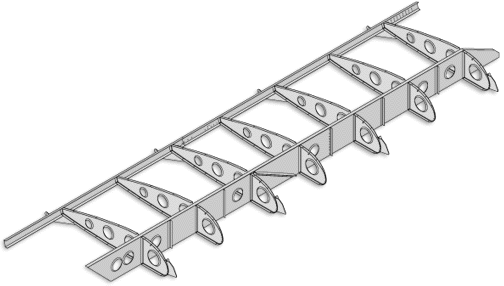
Do formula 1 teams have ribs and spars like the picture below?

Image

I don't think that is the case due to the extremely complex shape and their small size.
Moreover are the elements glued to the endplates? If so, how the can adjust the angle of attack?
and are the endplates the only support of the elements?

Thank you in advance for any information !

User avatar
turbof1
Moderator
Joined: 19 Jul 2012, 21:36
Location: MountDoom CFD Matrix

Re: Front Wing Assembly

Post

Oh my, this is where my drawings are exactly perfect for.

To answer your questions: let's take the Marussia front wing:
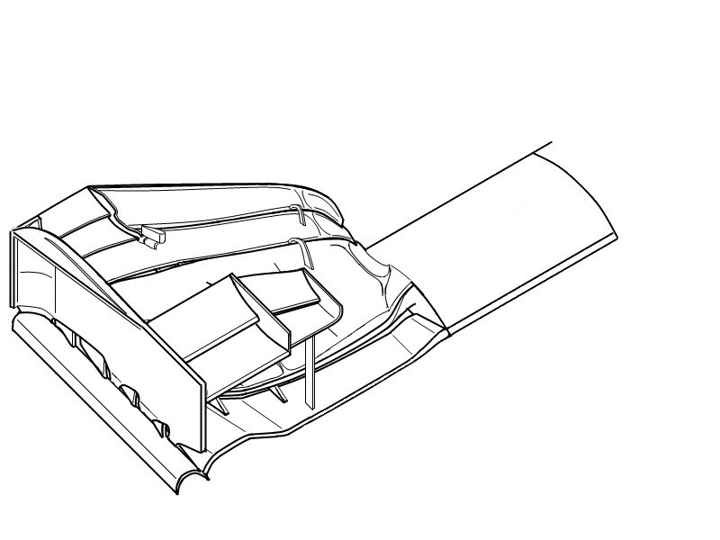
Image
The first thing you should note, is the little piece on of the upper flaps:
Image
This is a position where a mechanic would place his tool to adjust the flap angle of the upper flap.. It's connected through a screw to 2 plates. by screwing clockwise or counter clockwise, one plate will rotate up or down adjacent of the other plate.

Note that the upperflaps are actually divided into 2 specific regions: one outboard of the flap adjuster, and one inboard of the flap adjuster. The outboard region remains static and cannot have its angle adjusted. The reason why is that area is critical for the wheel wake, with its positions and shape optimized to tackle the issues as best as possible. Adjusting the angle in that area would move it outside that optimal position. The inboard region is not in front of the tyre, and thus has no or minimal effect on the wheel wake, making it adjustable.

Note that Marussia can only adjust the uppermost flap. Most teams have the mechanism adjusting the 2 uppermost flaps (together, not independantly).

To answer your question about structural support: the endplate usually does not provide critical support to the whole wing. Meaning that if it was to be knocked off and the rest of the wing does not receive damage, the rest of the wing will not break down (However, you'll probably not get through the flex tests), with the exception of the cascades, which do lean on the endplate for structural support. It will look like this:
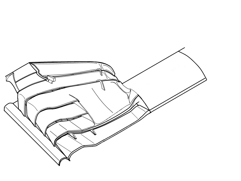
Image
So what does support the main wing? Let's dissassemble our Marussia wing:
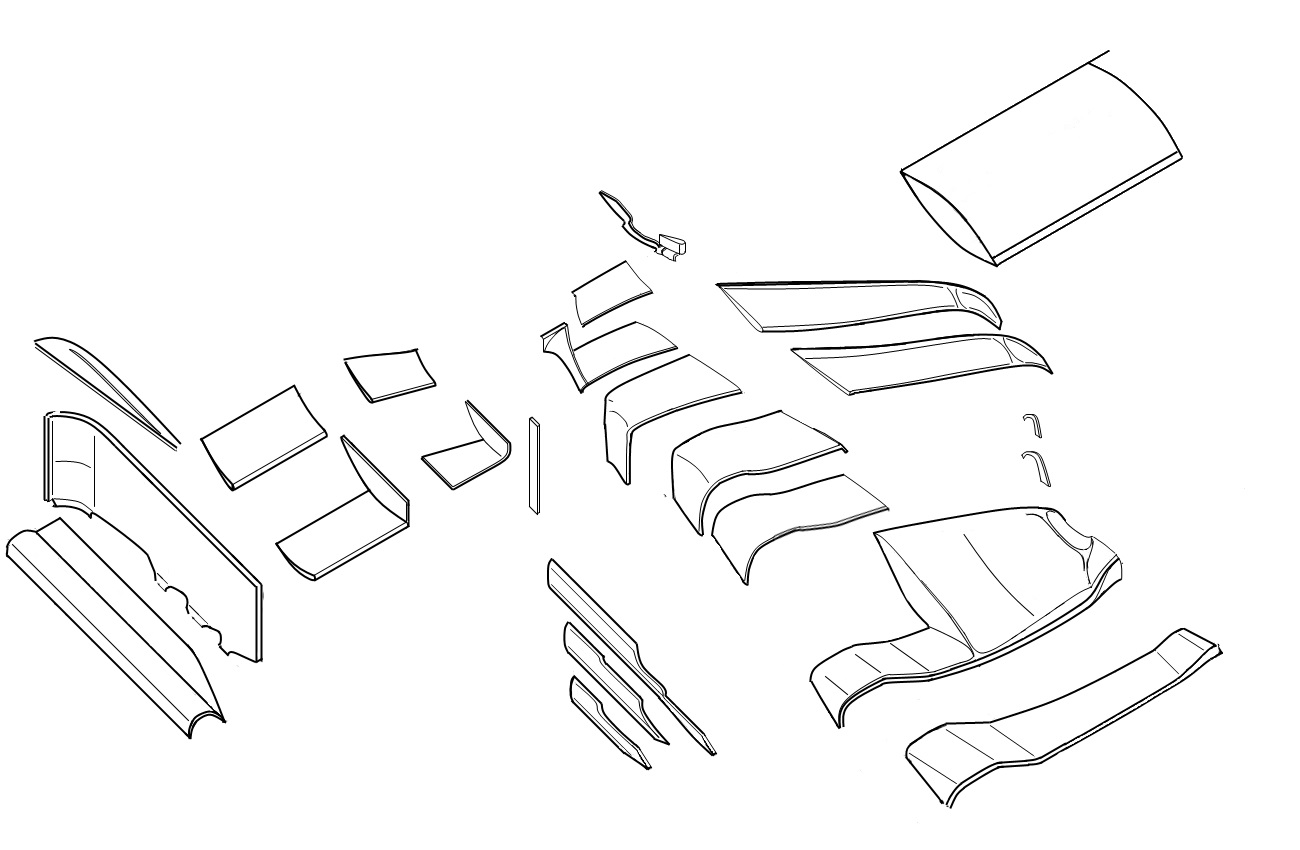
Image
There are 2 things you have to take notice of:
-The arched pieces provide support to the upper elements. This is more to give it some rigidity then to keep it the flap from ripping off. Still, in case of when the endplate breaks off, they can become important to keep it together.
-The 3 "stalks", longitudal pieces however are much important. They are what we call the underbody strakes and are as the name suggest, positioned underneath the wing. When you compare them with the other illustrations, you'll notice 2 stick out in front on top of the first element of the wing. Its shape then sticks to the undersides of the 2d, 3d and 4th outboard elements, providing critical support.

All the rest of the support is down to carbon layering.
#AeroFrodo

wesley123
204
Joined: 23 Feb 2008, 17:55

Re: Front Wing Assembly

Post

Afaik F1 wings don't have such internal ribs, instead, they are filled with some sort of foam if i'm correct.
"Bite my shiny metal ass" - Bender

User avatar
flynfrog
Moderator
Joined: 23 Mar 2006, 22:31

Re: Front Wing Assembly

Post

wesley123 wrote:Afaik F1 wings don't have such internal ribs, instead, they are filled with some sort of foam if i'm correct.
not sure wesly I've seen a broken indycar wing and it had ribs and foam in it. The foam is not as weight efficent as honeycomb though. When the cars crash I haven't noticed any foam or honeycomb in the debris. This would lead me to believe they are rib stiffened. Its surprisingly hard to find a good broken wing picture.

User avatar
flynfrog
Moderator
Joined: 23 Mar 2006, 22:31

Re: Front Wing Assembly

Post

ah ha you can see the foam (probably roacell) in this picture. Image

User avatar
turbof1
Moderator
Joined: 19 Jul 2012, 21:36
Location: MountDoom CFD Matrix

Re: Front Wing Assembly

Post

The thing is: that is inside the endplate, one of the thickest pieces on the wing. I don't think that for instance the very flat upper flaps have foam inside. I think that'll be pure carbon layering.
#AeroFrodo

User avatar
flynfrog
Moderator
Joined: 23 Mar 2006, 22:31

Re: Front Wing Assembly

Post

check out saubers cutaway you can see foam in all of the elements and at least some stringers probably a few ribs at the mounting points at least.

http://www.sauberf1team.com/fileadmin/u ... raphic.pdf

wesley123
204
Joined: 23 Feb 2008, 17:55

Re: Front Wing Assembly

Post

I'm not sure about the ribs but i remember seeing a Jaguar's rear wing breaking (I believe 2002)and a bit of foam was visible.
"Bite my shiny metal ass" - Bender

User avatar
RicME85
52
Joined: 09 Feb 2012, 13:11
Location: Derby
Contact:

Re: Front Wing Assembly

Post

Pretty sure you could see foam when the Hulks wing fell off at Hungary. There was stuff like when a polystyrene marker board gets hit.

riff_raff
132
Joined: 24 Dec 2004, 10:18

Re: Front Wing Assembly

Post

The complex shapes of F1 wing elements can be best constructed using foam cores and stressed skins. In theory, you might be able to produce a lighter/stiffer wing structure using spar/skin/rib construction, but it would not be worth the hassle.
"Q: How do you make a small fortune in racing?
A: Start with a large one!"

Robbobnob
33
Joined: 21 May 2010, 04:03
Location: Auckland, New Zealand

Re: Front Wing Assembly

Post

I would assume from a manufacturing perspective that the internal cells of the wing elements are manufactured from a method of rapid prototyping, be it traditional CNC machining or more modern 3D printing.

If 3D printing was being used, is it possible that they would create a lattice structure similar to multidimensional honeycomb structure, maximising stiffness to weight ratio?

Check out this article for an example of a Planar honeycomb structure constructed using a 3D printed epoxy resin, similar to the resins used in carbon composite layup technology.
http://www.gizmag.com/3d-printed-strong ... ite/32738/

A 3 dimensional lattice would be super strong in compression and would provide a very high stiffness structure to then lay up the composite sheets in high tension on the outside.
"I continuously go further and further learning about my own limitations, my body limitations, psychological limitations. It's a way of life for me." - Ayrton Senna

Cold Fussion
93
Joined: 19 Dec 2010, 04:51

Re: Front Wing Assembly

Post

Bear in mind they are only going for the minimum stiffness required by the regulations.

Robbobnob
33
Joined: 21 May 2010, 04:03
Location: Auckland, New Zealand

Re: Front Wing Assembly

Post

Cold Fussion wrote:Bear in mind they are only going for the minimum stiffness required by the regulations.
Certainly, but the structural stiffness is provided by the angle of the layup and the layup thickness for the laminate sheeting, and the foam / internal cells only provide structural stiffness to mould the shape around. Hence a stiffer material would require less mass to achieve the same effect.
Items like a crash structure could make use of the material to good effect also.
"I continuously go further and further learning about my own limitations, my body limitations, psychological limitations. It's a way of life for me." - Ayrton Senna

riff_raff
132
Joined: 24 Dec 2004, 10:18

Re: Front Wing Assembly

Post

The foam core only provides load transfer between the opposing composite skins. This mostly helps with buckling.
"Q: How do you make a small fortune in racing?
A: Start with a large one!"

Robbobnob
33
Joined: 21 May 2010, 04:03
Location: Auckland, New Zealand

Re: Front Wing Assembly

Post

Load transfer in compression. The foams are traditionally isotropic and have a very high positive poisons ratios ~0.31 and have a compressive strength in the order of 2.0 MPa and tensile strengths to the order of 4.0MPa. They are essentially a lightweight frame for laying up structural Carbon across, and don't particularly provide much structural properties.

Aluminium Honey comb is very interesting. Aluminium as a homologous material it has one of the highest poisons ratios, 0.34-0.35 and therefore provides good performance in both tension and compression. When this is combined with a planar geometry configuration such as the hexagonal honeycomb, its in plane poisons ratio is negative (approximately -1) due to the vectoring of the shear forces into tensile forces throughout the structure. It is this behaviour that is very good at distributing a tensile load through the core of the composite and transfer that into a hoop stress in the exterior layup. However this behaviour is only exhibited in-plane and thus the distribution of the load to the outer skin will be localised instead of being evenly distributed.

3 dimensional crystal lattices make use of this vectoring of shear forces into tensile forces to produce a super strong configuration, distributing forces both in plane and normal to plane. Because of this multidimensional distribution the poisons ratios are to the order of -2. This is also the reason why Diamond is so strong, with its super strong molecular bond strength orientated in a 3d tetrahedral crystal lattice, it shares the load very evenly.

Now back to point, using CNC controlled metal sintering, it would be possible to create a aluminium tetrahedral lattice which exhibited great in planar and through planar load distribution, transferring the forces much more evenly into the exterior carbon as a evenly distributed hoop stress, removing stress localisations, and increasing the overall duty of the entire cross section of the carbon structure.
"I continuously go further and further learning about my own limitations, my body limitations, psychological limitations. It's a way of life for me." - Ayrton Senna