Front Wing Assembly

Here are our CFD links and discussions about aerodynamics, suspension, driver safety and tyres. Please stick to F1 on this forum.
riff_raff
riff_raff
132
Joined: 24 Dec 2004, 10:18

Re: Front Wing Assembly

Post

The foam core material used in composite structures provides significant benefits in terms of strength and stiffness. The foam core functions in the same manner as aluminum or aramid honeycomb. Honeycomb is usually lighter than high density foam, but machining and laying-up honeycomb materials is much more difficult than high density foam. There is also the issue of honeycomb core having far less bond area with the inner skin surface than foam core. There is much greater difficulty in achieving a full adhesive bond over the entire interface between the honeycomb core edges and the composite skins than there is with high density foam core.

If the foam core provided no structural benefit, it would be just as easy to lay up the composite wing skins over a silicone bladder, and placed inside of OML tooling.
"Q: How do you make a small fortune in racing?
A: Start with a large one!"

n4rf
n4rf
34
Joined: 21 Apr 2015, 21:59

Re: Front Wing Assembly

Post

I'm pretty sure they mainly use foam (for example rohacell) and carbon, aluminium or titanium for additional ribs or at least as the inserts for mounting them and for the threads. I've seen wings made from 2 layers of cfrp and ribs of rohacell, but those wings didn't need to survive any really high loads or possible crashes.
I strongly doubt they're using honeycomb material, because it's very hard to achieve the perfect surfaces that they apparently produce with the uneven load distribution you get when the parts are in the mold. For a wing you usually use a 2 part mold that defines the outside and press the carbon fibre onto the core. That way it's easy to get really nice surfaces. It also makes the foam the obvious choice, because there is no danger of collapsing, which is always an issue when using honeycomb material. Also, machining of the foam is remarkably easy, so the production process is a lot faster. If you look at the speed teams are putting new wings out, I'd assume, they go for "easy" manufacturing and predictable behaviour (isotropic foam is easy to calculate for deflection, stiffness etc.).

polarboy
polarboy
4
Joined: 04 Dec 2009, 01:09

Re: Front Wing Assembly

Post

Most teams now do "ply stacking" for the front mainplane
Wing is made in 2 half's,cloth and U/D laminate
As you laminate it its hard to see what's happening as you seem to be stopping plies for no reason or adding in other areas
Both halves are made over size then machined down (400,000 lines of code on last years wing !)
Part is cold bonded together
This is how you end up with a stiff but flexi wing
All the flaps,cascades,endplates and footplates are rohacell but not just single parts
A simple looking endplate for example might have 6/7 foam parts
Laminates in both half's of the mould then all the edges of the foams will be wrapped with 2/3 plies of carbon
Where the foam joins you will then have a ready made internal I beam rib that cures as the part cooks

krisfx
krisfx
14
Joined: 04 Jan 2012, 23:07

Re: Front Wing Assembly

Post

polarboy wrote:Most teams now do "ply stacking" for the front mainplane
Wing is made in 2 half's,cloth and U/D laminate
As you laminate it its hard to see what's happening as you seem to be stopping plies for no reason or adding in other areas
Both halves are made over size then machined down (400,000 lines of code on last years wing !)
Part is cold bonded together
This is how you end up with a stiff but flexi wing
All the flaps,cascades,endplates and footplates are rohacell but not just single parts
A simple looking endplate for example might have 6/7 foam parts
Laminates in both half's of the mould then all the edges of the foams will be wrapped with 2/3 plies of carbon
Where the foam joins you will then have a ready made internal I beam rib that cures as the part cooks
Strange, an ex F1 engineer once told me that you should avoid machining carbon fibre, though ideas do change and this was a couple of years ago now.

User avatar
flynfrog
Moderator
Joined: 23 Mar 2006, 22:31

Re: Front Wing Assembly

Post

I think he is referring to the foam but I could be wrong.

polarboy
polarboy
4
Joined: 04 Dec 2009, 01:09

Re: Front Wing Assembly

Post

No refering to the actual mainplane section of the front wing,no foam in it and entire surface machined
Never heard anyone have a problem with machining carbon ? Not from a point of view of using it in a laminate anyway
Machine shops use to hate it due to the dust and use to claim it was bad for the working surfaces on the machines but now with the new enclosed machines with extraction there aren't any problems
Even 10 years ago you would find Ali inserts in the car for engine mounts,nosebox fixings an wing fixings.Now they are all ma chined carbon

User avatar
flynfrog
Moderator
Joined: 23 Mar 2006, 22:31

Re: Front Wing Assembly

Post

maybe I am not following you. So you are saying the mold the wing in two halves and bonding together this makes sense you get two molded surfaces then. Some closeout plies over the seam - makes sense. Then they machine the entire molded surface? I don't understand why you would do this you can hit just as good or not better surface profile out of a mold than you could machine. Also machining means you will be cutting plies and possibly not consistently leading to an unknown structural properties. I agree machining composite is not really a big deal but it seams like a complicated way to get a surface that could be molded.


Looking at the picture I ruthlessly stole from scarbs scarbsf1.files.wordpress.com it doesn't line up to what you are saying. the visible carbon is obliviously an unmolested molded surface.
Image

I can maybe make out a ply drop near the leading edge of this one but no evidence of machining the laminate surface.
Image

A machined surface would look more like this
Image

edit

one more picture of a merc wing I can see the ply drops but no surface profiling.
Image

Same on the Ferrari
Image

polarboy
polarboy
4
Joined: 04 Dec 2009, 01:09

Re: Front Wing Assembly

Post

First two pictures are a good choice as I made both those items !
You misunderstand what I'm saying your not machining the outer wing profile you are doing all the machining on the inside.
The laminate ends up as variable thicknesses across the wing,some parts will form in affect sort of ribs and spars where your glue join will be (you cant see the glue join on the leading or trailing edges as it has black pigment in it)
There are also a lot of hollow sections with a very thin skin section
There are also many "random" little hard pads ect which when your doing the first one you wonder what its for.
Its not till you have the wing in the assembly jig with the assembly drawing and you find out that something like the cascade with the CNN sticker in your picture will be fixed
Also no ply drop off or machining on any of the items in the first two pictures that's just where the moulds slit
The endplate in the second picture is 7 pieces of foam I'm memory serves' me correct so that's 5 internal rib's /i-beams in that area alone

User avatar
flynfrog
Moderator
Joined: 23 Mar 2006, 22:31

Re: Front Wing Assembly

Post

That makes more sense you are facing your bonding surfaces so the two halves meet up well.


Also word of caution we have had other F1 team member post about the work they do here and it didn't work out well for them. You may want to keep it more vague.

User avatar
DiogoBrand
73
Joined: 14 May 2015, 19:02
Location: Brazil

Re: Front Wing Assembly

Post

One question I have is:
Why do the pylons attach to the FW so far back on the Neutral section? And why do they extend back even when they're not attached to the wing anymore?
Image

User avatar
godlameroso
309
Joined: 16 Jan 2010, 21:27
Location: Miami FL

Re: Front Wing Assembly

Post

To guide airflow under the nose where it's then diverted under the floor and around the side pods and undercut.

Image
Saishū kōnā

noahtheporscheguy
noahtheporscheguy
0
Joined: 05 Jan 2015, 05:34

Re: Front Wing Assembly

Post

turbof1 wrote:Oh my, this is where my drawings are exactly perfect for.

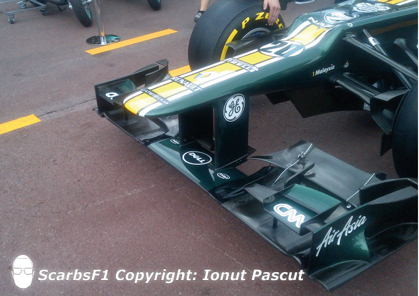
To answer your questions: let's take the Marussia front wing:
http://u.cubeupload.com/turbof1/Marussia.jpg
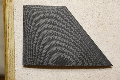
The first thing you should note, is the little piece on of the upper flaps:
http://u.cubeupload.com/turbof1/FlapAdjuster.jpg
This is a position where a mechanic would place his tool to adjust the flap angle of the upper flap.. It's connected through a screw to 2 plates. by screwing clockwise or counter clockwise, one plate will rotate up or down adjacent of the other plate.

Note that the upperflaps are actually divided into 2 specific regions: one outboard of the flap adjuster, and one inboard of the flap adjuster. The outboard region remains static and cannot have its angle adjusted. The reason why is that area is critical for the wheel wake, with its positions and shape optimized to tackle the issues as best as possible. Adjusting the angle in that area would move it outside that optimal position. The inboard region is not in front of the tyre, and thus has no or minimal effect on the wheel wake, making it adjustable.

Note that Marussia can only adjust the uppermost flap. Most teams have the mechanism adjusting the 2 uppermost flaps (together, not independantly).

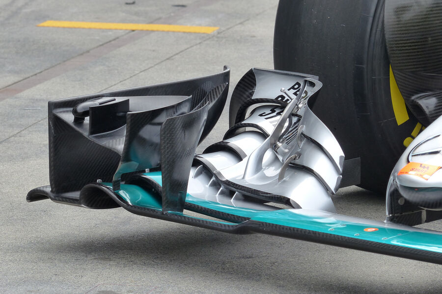
To answer your question about structural support: the endplate usually does not provide critical support to the whole wing. Meaning that if it was to be knocked off and the rest of the wing does not receive damage, the rest of the wing will not break down (However, you'll probably not get through the flex tests), with the exception of the cascades, which do lean on the endplate for structural support. It will look like this:
http://u.cubeupload.com/turbof1/MW.jpg
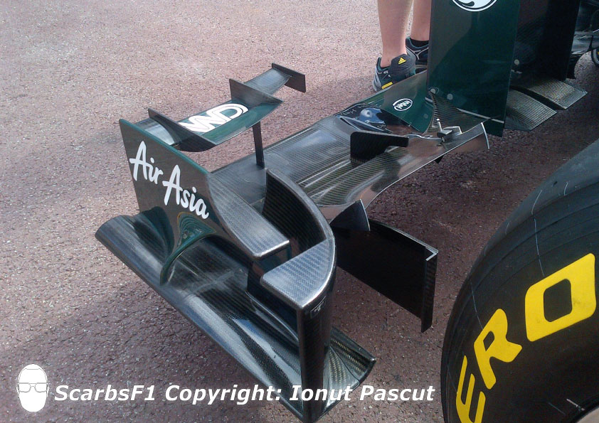
So what does support the main wing? Let's dissassemble our Marussia wing:
http://u.cubeupload.com/turbof1/Dissassembly.jpg
There are 2 things you have to take notice of:
-The arched pieces provide support to the upper elements. This is more to give it some rigidity then to keep it the flap from ripping off. Still, in case of when the endplate breaks off, they can become important to keep it together.
-The 3 "stalks", longitudal pieces however are much important. They are what we call the underbody strakes and are as the name suggest, positioned underneath the wing. When you compare them with the other illustrations, you'll notice 2 stick out in front on top of the first element of the wing. Its shape then sticks to the undersides of the 2d, 3d and 4th outboard elements, providing critical support.

All the rest of the support is down to carbon layering.
are these images still available? Would very much like to see