It looks like it can't be moved at all.
Does somebody have a schematic?

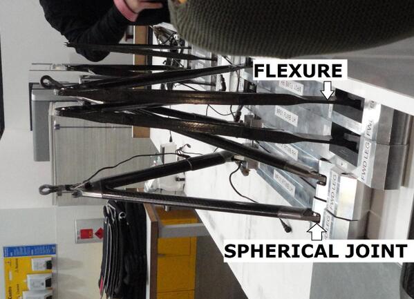
Thanks for sharing your knowledge!Scootin159 wrote: ↑17 Jul 2017, 21:44You're largely right. They use what's called a "Flexure" joint, which is basically a specially crafted pieces of composite material that is flexible (although still quite stiff) in one dimension, but all but immovable in the other two dimensions. You can somewhat get the idea by grabbing a notepad and trying to bend it - it will bend easily up & down, but it doesn't "compress" much at all, and it doesn't like being "twisted" (in the lateral plane) very much. Twisting in the vertical plane isn't really an issue, since there's always two of them per wishbone.
The reason they use flexures, as opposed to standard spherical bearings, is to eliminate stiction in the suspension. They are quite stiff (stiff enough you can't bend them by hand), so they do provide an element of a spring rate, but that's easily accounted for by just running softer main springs.
I should add that the joint itself is really just built into the end of the wishbone. One end is bonded to the rigid portion of the wishbone, and the other end is bonded to a titanium end piece. That end piece is then rigidly bolted to the chassis. The rectangular piece you see on the chassis where the wishbones connect is just a flexible aerodynamic cover - likely made of some type of thin plastic or rubber. The actual flexure mounting bolts would be under that cover.

They use flexures. Search for "F1 suspension flexures" and have a look at some images.daniellammers wrote: ↑17 Jul 2017, 19:41How are the wishbones connected to the car?
It looks like it can't be moved at all.
Does somebody have a schematic?
http://i.imgur.com/D528R00.jpg