Reducing the drag of a two element wing through stall

Here are our CFD links and discussions about aerodynamics, suspension, driver safety and tyres. Please stick to F1 on this forum.
Post Reply
czt
czt
0
Joined: 05 Mar 2009, 00:07

Re: McLarens Engine cover/fin

Post

autogyro wrote: If it is it will be the first time they have taken airflow in yaw into account.
Most designers still think the cars run strait all the time.
Whatever gave you that idea?

The engine covers of the last couple of years worked by increasing performance in yaw, but McLarens new one clearly has another trick up its sleeve.

autogyro
53
Joined: 04 Oct 2009, 15:03

Re: McLarens Engine cover/fin

Post

czt wrote:
autogyro wrote: If it is it will be the first time they have taken airflow in yaw into account.
Most designers still think the cars run strait all the time.
Whatever gave you that idea?

The engine covers of the last couple of years worked by increasing performance in yaw, but McLarens new one clearly has another trick up its sleeve.
I would say that the engine cover fins have helped to repair some of the negative aero results of yaw in the designs.
I do not believe you will find that the fins increase performance in yaw.

manchild
12
Joined: 03 Jun 2005, 10:54

Re: McLarens Engine cover/fin

Post

autogyro wrote:Most designers still think the cars run strait all the time.
+1

=D>

czt
czt
0
Joined: 05 Mar 2009, 00:07

Re: McLarens Engine cover/fin

Post

autogyro wrote:
czt wrote:
autogyro wrote: If it is it will be the first time they have taken airflow in yaw into account.
Most designers still think the cars run strait all the time.
Whatever gave you that idea?

The engine covers of the last couple of years worked by increasing performance in yaw, but McLarens new one clearly has another trick up its sleeve.
I would say that the engine cover fins have helped to repair some of the negative aero results of yaw in the designs.
I do not believe you will find that the fins increase performance in yaw.
A car is always going to have worse performance in yaw than in a straight line, as it will experience different conditions on each side of the car. The fin serves to ensure the rear wing works as best it can in these conditions. In some respects, the straight line performance is irrelevant, as you dont need downforce when barelling along the pit straight. I don't know what series you are referring to where most designers just think about straight line performance but it isn't F1!

ColinPowell
0
Joined: 27 Nov 2009, 02:37

Re: McLarens Engine cover/fin

Post

Have you seen Scarbs interpretation? http://scarbsf1.wordpress.com/2010/02/1 ... shark-fin/

He suggests that the opening near the airbox not only cools oil, but is tunneled within the bulbous sharkfin and on to the rear wing. The air acts to seperate the fins further, creating a 'third element' - allowing for increased angle without stall.

autogyro
53
Joined: 04 Oct 2009, 15:03

Re: McLarens Engine cover/fin

Post

I would like to see some of these clever fluid flow print outs, that show a car in a turning condition.
All I have seen so far are cars going in a strait line with lots of complex math.

User avatar
PlatinumZealot
552
Joined: 12 Jun 2008, 03:45

Re: McLarens Engine cover/fin

Post

ColinPowell wrote:Have you seen Scarbs interpretation? http://scarbsf1.wordpress.com/2010/02/1 ... shark-fin/

He suggests that the opening near the airbox not only cools oil, but is tunneled within the bulbous sharkfin and on to the rear wing. The air acts to seperate the fins further, creating a 'third element' - allowing for increased angle without stall.
Scarbs got it right from here. Autosport forums also stole it from here too. This was the first forum with it as far as I know.
🖐️✌️☝️👀👌✍️🐎🏆🙏

User avatar
PlatinumZealot
552
Joined: 12 Jun 2008, 03:45

Re: Reducing the drag of a two element wing through stall

Post

In fluid dynamics, a stall is a reduction in the lift coefficient generated by an airfoil as angle of attack increases.
That is from wiki.

This is what I was saying from the mclaren thread; we should not use the word stall because from this definition Stall is related to angle of attack, and from graphs of airfoil profiles that show stall, they have Angle of attack as the variable on the X axis. This won't apply because In formula 1 the rear wing is FIXED.

We can't compare it to a plane wing just like that.
The definition that we have to use is something like:

A reduction in lift coefficient generated by an airfoil as ______( injecting high pressure air under the wing..)..something to that effect.

I hope this makes sense.
🖐️✌️☝️👀👌✍️🐎🏆🙏

User avatar
ringo
227
Joined: 29 Mar 2009, 10:57

Re: Reducing the drag of a two element wing through stall

Post

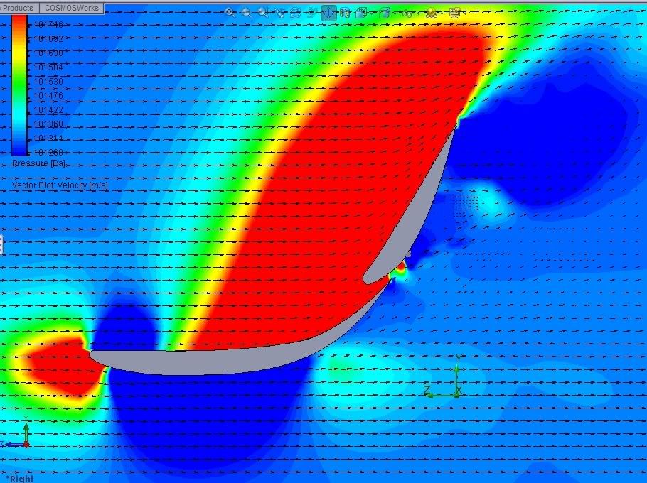
I drew a 2 element wing and ran it at 90m/s; over 200mph. This wing is my creation, it may as well be rubbish :lol:

Image
^^Standard wing, no blown flap. this is velocity not pressure, (do not use this to visually determine where the high pressure is, there are density changes as well.)
Image
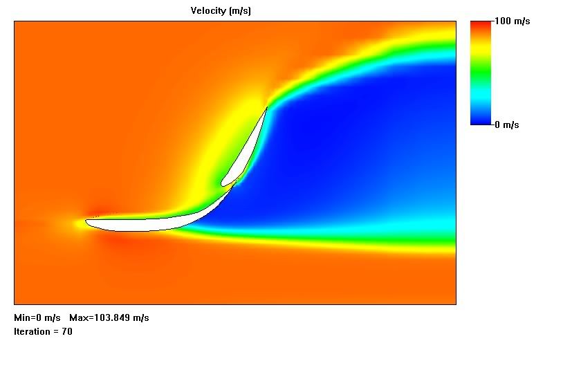
^^tangential blowing.
observations, blowing tangential to the 2nd element surface, 90m/s 1atm.

1) no effect on top of main element, though slot is less choked. The separation point is move slightly backward beneath mean element.

2) no major difference to boundary layer, maybe reduces it's thickness which is very minsicule.

3) Slight difference in velocity gradient near trailing edge, and has a pull on the air on the front side of 2nd element, changing velocity gradient there as well.
4) wake is unchange.

What I observed is that, blowing at the second element does little to change the wing performance. Reason being the velocity is already high on the elements surface,and there is no danger of separation because of the strong up-wash coming through the slot.
I also observed that the boundary layer seemed to be quite small, which is good. No major differences though.

From observing the existing flap blown planes, flap blowing is best done in the slot. Having it at the middle of the second element is just in the wrong place. It would do well in the slot or on the bottom of the first element. It is also meant for blunt thick trailing edges where separation occur, such as in the pocket of a wing where the flap retracts in.

So with the understanding that blowing tangentially to the elements surface is redundant because the boundary layer is already highly energized; I angled the blowing away from the surface.
Image
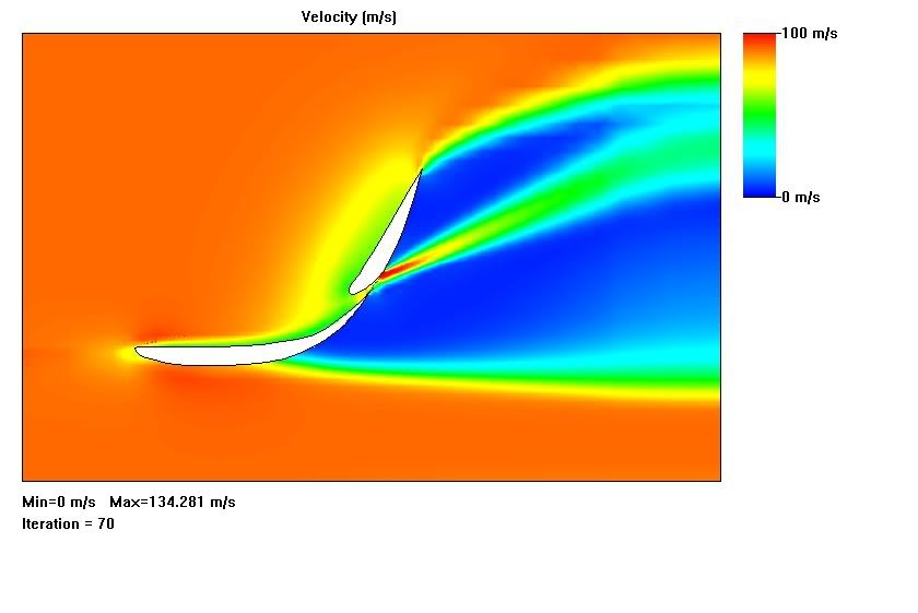
^^blowing at an angle
This of course "stalled"?? the element leaving a detached boundary layer on the back side of the element.

observations for blowing at and angle at 90m/s, 1atm. and 373k :

1) Though the air jet was at free stream pressure, it quickly diffused to the local pressure immediately behind the wing.

2) The off shot jet was diverting the flow from off the wing and out into the wake. leaving a stalled area on the element surface downstream of the jet.

3)The wake was being noticeably distorted by the jet.

What i realized from this is the fact that the element stalled has little to do with the total outcome on the drag. The stalling takes place in the wake because of the almost vertical element. It does not increase the size or height of the wake.
This is slightly different than an aircraft, where the wake is slightly behind and stalling of the top surface can increase the wake size.

The whole point is not realy stalling the wing. Stalling is part of it. I think the bigger picture is passive wake control. The angle of upwash from the wing is virtually an extention of it's angle of attack. The up wash is also connected to the wake. If the up wash is pulled in, it will virtually reduce the AOA and the drag. Varying jet speeds will pull on the wake with varying strength.

This slot more than likely jets air outward from the element into the wake and distorting it, maybe that is why we saw that gap in the flow vis, the flow shot off into the wake.

I got some results, which could be completely off because of the size of the computational domain that i use. My PC crashed a couple times looking for the right level of detail.
The reductions in down-force were very small, and reduction in drag was also small.The made up wing has a L/D ratio of 0.9148 .

from normal flap to blowing tangentially: Lift/Drag ratio 0.91566 ,.32% drag reduction, .229% DF reduction

from normal flap to blowing into the wake: L/D 0.9128, .5% drag reduction, 0.71% DF reduction

And remember my wing profiles are made up!, this is not a true reprsentation! :mrgreen:
These numbers and opinions are also to be taken with a grain of salt!!! I jut put them there to give an idea of the scale of the improvements.
For Sure!!

User avatar
horse
6
Joined: 23 Oct 2009, 17:53
Location: Bilbao, ES
Contact:

Re: Reducing the drag of a two element wing through stall

Post

Woh! Good work Ringo! I'll have a better look at it tomorrow, but on first impressions with the model, is it normal to have no flow at the back of the wing? Does it just make a big hole there?
I also thought that the flow seems to be detaching from the lower element too early which is perhaps not right. My thought was that the lower element feeds the upper element, but I could be wrong. Anyway, this post puts a spanner in the works from the MP25 thread:
kalinka wrote:Just an addition to the rear aero debate :

http://www.formula1.com/news/technical/2010/0/720.html

I think though that it's more confusing than explaining :)
This might tally with an idea that I had, but I'm just going to draw it and scan it in tomorrow. I'll print off your post as well, Ringo and have a better look at it. I'm surprised how little difference blowing made, however. If the made up wing has a L/D ratio of 0.9148, that is very small, no? You may just have a stalled wing, which the blowing would make no difference to.
"Words are for meaning: when you've got the meaning, you can forget the words." - Chuang Tzu

User avatar
ringo
227
Joined: 29 Mar 2009, 10:57

Re: Reducing the drag of a two element wing through stall

Post

horse wrote:Woh! Good work Ringo! I'll have a better look at it tomorrow, but on first impressions with the model, is it normal to have no flow at the back of the wing? Does it just make a big hole there?
I also thought that the flow seems to be detaching from the lower element too early which is perhaps not right. My thought was that the lower element feeds the upper element, but I could be wrong. Anyway, this post puts a spanner in the works from the MP25 thread:
kalinka wrote:Just an addition to the rear aero debate :

http://www.formula1.com/news/technical/2010/0/720.html

I think though that it's more confusing than explaining :)
This might tally with an idea that I had, but I'm just going to draw it and scan it in tomorrow. I'll print off your post as well, Ringo and have a better look at it. I'm surprised how little difference blowing made, however. If the made up wing has a L/D ratio of 0.9148, that is very small, no?
I was looking at that too,

This may help as well.
Image
^^(This is the plot for blowing at an angle by the way)

I was wondering if that is the case with these high camber wings, normally a nother element would help keep the flow attatched down there.
This is why i said earlier that blowing on the first element is more beneficial. You can see where it would help.
Slot in the first element:
Image
^^#6.
borrowing from bar555 again. :oops:

This would effectively behave like a third element.
For Sure!!

Pup
Pup
50
Joined: 08 May 2008, 17:45

Re: Reducing the drag of a two element wing through stall

Post

n smikle wrote:
In fluid dynamics, a stall is a reduction in the lift coefficient generated by an airfoil as angle of attack increases.
That is from wiki.

This is what I was saying from the mclaren thread; we should not use the word stall because from this definition Stall is related to angle of attack, and from graphs of airfoil profiles that show stall, they have Angle of attack as the variable on the X axis. This won't apply because In formula 1 the rear wing is FIXED.

We can't compare it to a plane wing just like that.
The definition that we have to use is something like:

A reduction in lift coefficient generated by an airfoil as ______( injecting high pressure air under the wing..)..something to that effect.

I hope this makes sense.
Yes that is all correct, but we're talking about changing the conditions with the blown wing. So you create a wing with an angle of attack like you say which would stall because the angle is to severe, but then add the blown slot, keeping it from doing so. That much is proven stuff that's used all the time in the real world. But the hypothesis here is that on the straight, either the blowing is cut off, or the effect is overcome in some other way, and the wing stalls.

You're correct that an F1 wing is little like an airplane wing. But for that very reason, I wouldn't get too caught up in the wikipedia explanation of things.

Pup
Pup
50
Joined: 08 May 2008, 17:45

Re: Reducing the drag of a two element wing through stall

Post

Ringo, in your diagrams, isn't the bottom wing already in a stalled state? If the bottom element is already stalled, the upper element doesn't stand a chance, no matter what you do.

I agree that the bottom element is probably blown, too - see my post in the 25 thread.

User avatar
ringo
227
Joined: 29 Mar 2009, 10:57

Re: Reducing the drag of a two element wing through stall

Post

Pup wrote:Ringo, in your diagrams, isn't the bottom wing already in a stalled state? If the bottom element is already stalled, the upper element doesn't stand a chance, no matter what you do.

I agree that the bottom element is probably blown, too - see my post in the 25 thread.
No, the upper element is fed by the slot, look carefully at the colour. It's almost impossible to stall the upper element, that slot is shooting air right along it. only when the slot is closed off or the element is blown at an angle that element will stall.

The bottom element, i don't really know about. Should it have that separation there or not, no one really knows because there has never been a velocity plot of a current F1 wing online.

The bridge wing is another factor i haven't considered. It's up-wash could keep the flow on the 1rst element attached too.
For Sure!!

Pup
Pup
50
Joined: 08 May 2008, 17:45

Re: Reducing the drag of a two element wing through stall

Post

My understanding is that the wings are coupled, and the gap between the two does much what a blown wing might do - reenergize the boundary layer. But if your airflow is separating where it is, you've already lost any ability to do that.

Post Reply