The inlet diffuser in this diagram depicts a separation angle of like 30+ degrees, so I don't see how it doesn't just separate at the entry.
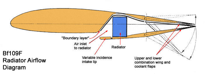
Radiators tend to function on pressure difference and low speed flow through the radiator – though turbulent radiator flow would be an interesting topic. The divergent inlet slows the flow and increases the pressure more or less in accord with the X-section increasing area of the diagram. Slower flow fills the increasing volume in front of the radiator and pressure difference drives the flow across the radiator. The heated air is then reaccelerated through the converging outlet.Cold Fussion wrote:I was talking about the diffuser before the radiator. I assume it must also have a variable geometry, but I can quite see how it works from that image. Similarly, if we look at the ducting for the BF109 F:
http://109lair.hobbyvista.com/techref/s ... irflow.jpg
The inlet diffuser in this diagram depicts a separation angle of like 30+ degrees, so I don't see how it doesn't just separate at the entry.