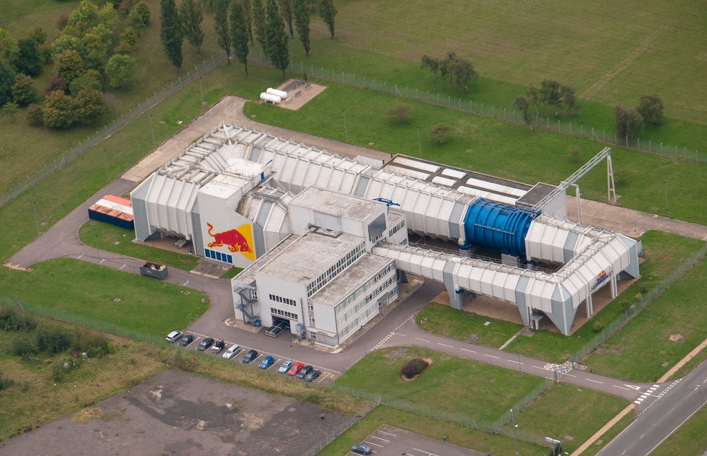
Sauber Wind Tunnel


Video was posted on previous page
Sauber Wind Tunnel specification
Code: Select all
The wind tunnel is designed as a closed circuit, measuring 141 metres in length (without the test section) and with a maximum tube diameter of 9.4 metres. The overall weight of all the steel elements plus the fan housing comes to 480 tonnes. The single-stage axial fan with carbon rotor blades uses 3,000 kW at full load.

At the heart of any wind tunnel is the test section. Both its diameter and the length of the rolling road are generously sized to provide optimal conditions for precise results. Testing with the actual racing car is technically possible, but tends to be the exception due to the regulations. Work is carried out almost exclusively using 60-percent scale models.

To allow the test models to be exposed to the air stream not just frontally but at an angle of up to ten degrees as well, the entire measuring platform can be rotated. The platform features a rotating steel belt which simulates the relative motion between the vehicle and the road and which runs in sync with the flow of air. Load cells are mounted under the belt to measure wheel loads.

Externally, the elegant wind tunnel building appears as a homogeneous hall, whereas in fact it consists of clearly separate elements: the actual wind tunnel and a wing with work offices and an event platform where partners and sponsors can hold events in a unique setting. The first-floor gallery has room for 150 guests.

This area is divided from the technical section by a glass wall, which ensures that the visual link is preserved while insulating it against the noise from the wind tunnel. Code: Select all
The Wind Tunnel looks like a large cylinder placed horizontally and closed at both ends by a Cshaped tubular duct. In this tunnel, the airflow is created by a turbine fan with a power of 2,200 kW, while sophisticated equipment keeps the temperature range down to 0.5 °C. The electronic system of recording and processing of analogical and digital data regarding the acting forces and the speed, direction and turbulence of the wind is in constant implementation.

Its central element is the tubular duct 80 metres in length where a flow of air is generated that is high quality in terms of turbulence, angularity and uniformity. The turbine guarantees an airflow of about 250 kph for models in 1:2 scale and about 150 kph for life-size models and real vehicles. Thanks to a mechanism controlled by over 300 sensors and a conveyor belt synchronized with the wind speed, it is possible to simulate and monitor on the models all attitudes and movements when they are in motion: rolling, yawing, pitching and swerving.


[youtube]http://www.youtube.com/watch?v=D1jCbH8bZ4Y[/youtube]
Video 2
TMG Wind Tunnel

Click for the full datasheet - TMG wind tunnel services
Code: Select all
Wind Tunnel specification
Dimensions: 63 x 26 x 13m
Test Section: 15 x 4.1 x 3.7m
Max. Wind: Speed 70m/s
Fan Diameter: 6.3m
Fan Power: 2.3MW
Accuracy: ±0.04%
Repeatability: ±0.02%

Rolling Road
Max. Speed: 70m/s (252kph)
Width: 2.4m
Length: 7m

Vertical Wheel Force Measurement
Load Range (model): 30-300N
Load Range (full-size, front): 50-500kg
Load Range (full-size, rear): 70-700kg

Overhead Balance
Drag: 1,800N
Side Force: 1,400N
Lift: 5,200N
Roll Moment: 1,100Nm
Pitch Moment: 2,600Nm
Yaw Moment: 1,100Nm

Model Motion System
Drag: 1,500N
Side Force: ±750N
Lift: 3,200N
Roll Moment: ±200Nm
Pitch Moment: ±26,000Nm
Yaw Moment: ±250NmDallara Wind tunnel
The new 60% version of WT was used by Ferrari in previous years

Code: Select all
General:
- 50% to 60% scale models
- Single return closed-circuit
- Dimensions: 46m long x 15m wide x 7m high
- Rectangular air path perimeter along centreline:100m
- Construction material: steel
Model Scale:
- 50% models for Sport and Touring Cars
- 50% to 60% models for F1 and IndyCar
Test section:
- Area: 7.5m
2
- Dimensions: 2.23m high x 3.35m wide x 8m long
- Slotted-wall (27% open)
Fan:
- Axial fan 4.1m diameter
- Fan DC motor power: 688kW
Moving belt:
- Length 5.4m
- Width 2.2m
- Automated Yaw +/- 6 degrees
- Active tensioning and tracking controls
- Water-cooled belt plate
- Distributed belt suction system
- Upstream boundary layer suction
- Boundary layer displacement thickness at model nose: 0.2mm
Speed:
- Wind: nominal 50 m/s
maximum 60 m/s
- Belt: nominal 50 m/s
maximum 70 m/s
- Turbulence level 0.2 %
Settling chamber and nozzle:
- Cooling system (water radiator): constant operating temperature 25°C
- Honeycomb and 3 fine screens
- Contraction ratio: 6 :1
Model support:
- Robotic-like 4 degrees of freedom automated remote control:
Heave and Pitch by hydraulic actuators
Yaw and Roll by electric motors
Adjustable longitudinal position
- Twin strut in tandem, twin streamlined cover
- Wide range of static testing capabilities
- CAM (Continuos Acquistion Mode) capability
Instrumentation:
- 7 component internal chassis balance
- 4 wheel drag balances
- Pressure measurement: PSI electronic scanner (160 ports)
Control and data acquisition system, data post-processing:
- Hardware: PC Windows based
- Software: Dallara In-House (acquisition & post-processing)
Optional Model Upgrades:
- Wheel-On configurations with 2 component Load Cells
- Automated Steer System
- Laser Ride Height Control Some old info from 2005 about the Mercedes (ex Honda) WT construction Link
Code: Select all
Q: Where is the new wind tunnel being built?
GM: "On site here in Brackley. We have demolished an existing unit to make way for the new three-storey building that will house the wind tunnel."

Q: When did work start on the project, is it still on schedule and when will it be fully functional?
Graham Miller: "Construction began on site exactly a year ago, in December 2004, by starting to dismantle the existing factory unit to make way for our new facility. The programme is absolutely on schedule and we plan to be productively testing in July 2006."

Q: What does a wind tunnel cost and do you need a specialist company to build it?
GM: "A full scale facility such as ours costs in the region of £30m. The wind tunnel itself is a specialist piece of kit, as is the 'rolling road' system on which the test vehicles sit, so it is a very technical and complex construction project in which the building constructor needs to work concurrently with the airline manufacturer and rolling road provider. Excellent teamwork and communication is essential in getting the project completed within the minimum timeframe."

Q: How big are the fans and how powerful are they?
GM: "The main fan has a blade diameter of over 5m and is powered by a 3,000 horsepower electric motor, generating a torque of 32,000 ft-lb at 500 rpm. In total there are 16 rotating blades and 27 stator blades - non-rotating blades that are a structural part of the fan construction. This fan will move around 1000 m3 of air per second so we'll be getting wind speeds of 80 metres per second in the test section!"

Q: What else will be included in the building?
GM: "Obviously there will be the wind tunnel itself plus all its associated plant, including drive cabinets for the fan and rolling road, electrical transformers, air compressors and vacuum pumps, as well as a fully-integrated manufacturing facility. In addition, there will be a fully-equipped server room which houses the servers for the wind tunnel plus provides an essential disaster recovery facility for the site as a whole in the event that something should happen to the main server room in the main HQ building, plus a museum and a presentation suite so that we have an impressive environment in which to entertain our guests as well."

Q: Honda Racing F1 Team already has a half-scale wind tunnel at Brackley; what are the advantages of a full-scale facility?
GM: "With good execution, the full scale tunnel will be vastly superior in terms of accuracy. It's what we call a 'closed-jet' tunnel which generally gives you a better quality of air flow. In the ongoing quest to improve the accuracy of the aerodynamic test data, the trend is towards large scale models which give better reproduction of vehicle surface features and higher accuracy. This naturally demands large-scale test sections which leads to higher capital costs and, ultimately, higher operating costs.

"The existing Honda Racing F1 Team smaller scale wind tunnel is different: it has an 'open jet' configuration. As the name suggests, open jet tunnels have an open test section in which we can remove the two walls and ceiling. In principle, the jet allows the flow field around the model to relax to something close to that experienced in ‘free air’ on the track. Another advantage is that it offers increased visibility and access for the test engineer. The disadvantage with open jet tunnels is that outside forces can affect the airflow in an unpredictable way. Aerodynamic test data is not generally as accurate as that obtainable from full scale, closed jet tunnels.

"The ultimate goal is the achievement of a near perfect match between the flow field generated in the wind tunnel with that in free air. To achieve this, our new tunnel features a test section with walls that can be shaped to vehicle contour and yaw angle."Q: What conditions can you simulate in a wind tunnel?
GM: "A good wind tunnel is an essential component of a successful Formula One team. They provide measurements for both downforce and drag, which have a major effect on the overall performance of the car. But I think it’s fair to say that teams are still some way from replicating a car’s behaviour on the track from inside a laboratory, which is effectively what a wind tunnel is. The major test equipment in the wind tunnel customised to work on a Formula One car is the rolling road section, which is needed to simulate the strong aerodynamic effect associated with the car moving close to the ground. The rolling road is itself within a turntable so that we can skew the car towards the wind. This has a major effect on downforce because when a car comes to a corner it will find itself at an angle. If your car suddenly drops off in downforce right when you need it, then you’re in a bit of trouble!

"Reproducing wind tunnel performance on the track is the key and, in the end, is what it is all about."
AeroLab WT specification
Code: Select all
The Main Features of the Aerolab Wind Tunnel

The Aerolab moving-belt wind tunnel, is a steel made rectangular section closed circuit with a single return duct. The wind tunnel is 46m long, 15m wide, and 7m high. The centreline of its rectangular air path perimeter is 100m long. The test section is 3.35m wide, 2.23m high and 8m long and its area is 7.5m².

A key component is the axial fan with a 4.1m diameter powered by a 610kW DC motor.
The nominal speed of the air and of the moving belt is 50 m/s, their maximal speed is over 55 m/s.
The moving belt is 2m long by 5.4m wide and has a nominal lifetime of 500 hours. It has an active tensioning and centering control, a water-cooled belt plate and a distributed belt suction system.
There is a boundary layer suction system installed on the upstream part of the moving-belt. The displacement thickness of the boundary layer is 0.3mm at model nose.

The settling chamber has an air cooling system (water radiator) that allows the temperature to remain constant (the nominal air temperature is 25°C), a honeycomb and two fine screens. The nozzle has a contraction ratio of 6:1.
In the test section the turbulence level is equal or inferior to 0,1%.

Here are the features of the model support, a 4 degrees of freedom remote controlled robot (FondTech
Step 3):
• Heave and pitch are controlled by hydraulic actuators
• Yaw and roll are controlled by electric motors
• Adjustable longitudinal position of the model inside the test section
• Twin strut in tandem with streamlined fairings
• Wide range of static testing capabilities
• Dynamic testing capabilities (heave and pitch up to 15Hz)

The wheels of the model are independently supported :
• Each wheel support is fully remote controlled (3 degrees of freedom + variable preload).

Regarding instrumentation and data acquisition:
• FondTech six component internal chassis balance
• Two component balance for each wheel
• Pressure measurement: PSI electronic scanner (2x64 ports).

The wind tunnel control, data acquisition (FondTech Alizé©) and data processing (FondTech Mapper©) software are installed on three PCs using Windows operating system.
The Aerolab wind tunnel, including all of its systems, have been designed by FondTech.RCE wrote:Force India has had its own wind tunnel facility at Brackley since 1997. In 2006 the largest model that the Brackley wind tunnel could accommodate was 40% scale. In order to improve its aerodynamic development capability, Midland decided to upgrade the wind tunnel to accommodate a 50% model. This involved taking the tunnel out of operation for several months. During this period a wind tunnel in Huntingdon operated by Lola Cars was rented. A 50% scale model was run in the Lola tunnel for the first time in about November 2006. It was immediately appreciated that the Lola tunnel could not satisfactorily cope with the weight of the model, causing problems with the data sampling system.


If you fallow the link "RCE"in the quote you can read full LotusF1 (Caterham) vs FI trial
Lola Wind Tunnel Specification
Code: Select all
Technical Data
-	Maximum model scale - Typically 50% for open wheel
-	Maximum model elevation - 600 millimetre gap above rolling road surface
-	Maximum wind speed - 65metres/second (145mph)
-	Maximum road speed - 80 metres/second
-	Turbulence intensity - <0.08%
-	Average wind temperature - 20º (70ºF)
-	Wind temperature stability - < 1º during test
-	Rolling road temperature - 14ºC (58ºF) ±0.5 ºC
-	Test section configuration - 2.70 metres wide x 2.47 metres high
-	Diffuser configuration - 7:1 contraction ratio
-	F an configuration Lola-designed and built 5-blade carbon composite unit
-	Main fan drive motor - 650kW (872hp)
-	Overhead balance 6-component unit with accuracy >0.04% of range
-	Model attitude control - Pitch, heave, roll, yaw, wheel steering
-	Rolling road area - 2.0 metres wide x 4.0 metres long
-	Rolling road motor - 200 kW (268hp)
-	Rolling road yaw angle - ±10º
-	Rolling road sensors - 4 pressure and 4 temperature
Lola 50% Scale Aerodynamic Wind Tunnel is presented in the following paper 2000 Society of Automotive Engineers - The Lola Wind Tunnel
Windshear Inc. Wind Tunnel
Used by Lotus F1 for full scale test in 2012

[youtube]http://www.youtube.com/watch?v=RAPt5jJbqcM[/youtube]
Wind tunnel specification &
Here for rolling road specs
More on Link