1991 & 1992 F1 Front Wing Regulations

Here are our CFD links and discussions about aerodynamics, suspension, driver safety and tyres. Please stick to F1 on this forum.
OO7
OO7
171
Joined: 06 Apr 2010, 17:49

1991 & 1992 F1 Front Wing Regulations

Post

The 1988 and 1994 F1 technical regulations are available online, but I'm trying find information on front wing regulations for 1991 and or 1992.

In 1990 I believe the minimum height of the front wing was at the same level as the geometric/reference plane (zero millimetres). According to a couple of online websites, from the 1991 season the minimum height of the front wing (bodywork including end plate) was increased to 25mm above the ref plane. Looking at images and videos of cars from that period, it appears that at some point ahead of the front wheel centreline, the front wing is at 25mm, but at some point behind it up to the rear edge of the front wheel, the body work (usually fitted with a titanium hooved strake, that is in contact with the ground at lower ride heights consistent with higher speeds) it seems was at the same level as the reference plane.

Can anyone confirm that this is accurate?

In 1994 the front wing was regulated to 40mm above the ref plane and I believe this rule was introduced in 1993. This rule however (according to the 1994 regs) stipulates that the front wing (body work from the rear edge of the front wheel to the front of the car, excluding the nose) has to be at least 40mm above the ref plane.

Also back then, how were teams able to fit titanium skid blocks to their cars, as I see no provisions for it in the regs and the same regs state that no sprung part of the car can sit below the ref plane. I'm wondering whether they exploited the +/-5mm tolerance allowed for the under body?
Last edited by OO7 on 10 Dec 2015, 16:58, edited 4 times in total.

OO7
OO7
171
Joined: 06 Apr 2010, 17:49

Re: 1991 & 1992 F1 Front Wing Regulations

Post

The following images show the part of the front wing mentioned in the post above:
Image
Image

User avatar
DiogoBrand
73
Joined: 14 May 2015, 19:02
Location: Brazil

Re: 1991 & 1992 F1 Front Wing Regulations

Post

Since we're on the subject of 1990's front wings, I'd like if someone could also explain the endplate shape used by williams during the early 90's. Why is the top of it on that V shape? Wouldn't that allow for some high pressure spillage? Anyway I'd be curious to know the reason for that.
Image

SuperDrummer
SuperDrummer
0
Joined: 29 May 2014, 22:57
Location: Saint-Petersburg

Re: 1991 & 1992 F1 Front Wing Regulations

Post

Blaze1 wrote:The following images show the part of the front wing mentioned in the post above:
http://i.imgur.com/JVqnOtC.png
I'm afraid you're mixing up reference plane and the monocoque. It was already a kind of "high nose", although not as high as the one used by Tyrrell.
You can see it here, for example.

Image

Image

I would wait for an aero expert regarding the V-shaped end plate, but we should keep in mind, that a lot of aero concepts were products of "thought experiment", not the results of wind tunnel testing. E. g. Jordan 196 sidepods as a typical example. So probably the real effect of the V-shaped end plate and the idea behind it might differ.

bhall II
bhall II
473
Joined: 19 Jun 2014, 20:15

Re: 1991 & 1992 F1 Front Wing Regulations

Post

Blaze1 wrote:Looking at images and videos of cars from that period, it appears that at some point ahead of the front wheel centreline, the front wing is at 25mm, but at some point behind it up to the rear edge of the front wheel, the body work (usually fitted with a titanium hooved strake, that is in contact with the ground at lower ride heights consistent with higher speeds) it seems was at the same level as the reference plane.

Can anyone confirm that this is accurate?
I think you're seeing this...

Image

It's a turning vane that was likely used to keep ground-level wheel wake from going under the floor.
DiogoBrand wrote:Since we're on the subject of 1990's front wings, I'd like if someone could also explain the endplate shape used by williams during the early 90's. Why is the top of it on that V shape? Wouldn't that allow for some high pressure spillage? Anyway I'd be curious to know the reason for that.
That's exactly why. End plate vortices create downforce, because they keep air flow attached to the suction surface of the wing (underside) at high angles of attack. Greater high-pressure flow = stronger vortices = more downforce.

Image
F2004

Honda's IndyCar design takes the concept to an entirely different level...

Image

trinidefender
trinidefender
317
Joined: 19 Apr 2013, 20:37

Re: 1991 & 1992 F1 Front Wing Regulations

Post

Bhall I'm still not convinced by your total and absolute theory that more air spillage creates more downforce. There is a fine line between enough to generate at vortex to keep flow attached on the wing and create a low pressure zone (as a result of the vortex) and too much that just increases overall pressure underneath the wing reducing pressure differ ethical between the sides of the wing and hence reducing downforce.

I still believe you have oversimplified the issue with flow going around the wing. If it was an absolute like you said then running with no endplate at all would be more beneficial and increasing the ride height would be more beneficial as it allows more flow underneath. Neither of these is true.

The indycar wing has two vortices underneath the wing. Flow going around the outside of the wing will only feed the outer vortex underneath the footplate. The vortex on the inside of the endplate, what I previously referred to as a tunnel, creates a vortex simply by the shape of the wing.

bhall II
bhall II
473
Joined: 19 Jun 2014, 20:15

Re: 1991 & 1992 F1 Front Wing Regulations

Post

trinidefender wrote:I still believe you have oversimplified the issue with flow going around the wing. If it was an absolute like you said then running with no endplate at all would be more beneficial and increasing the ride height would be more beneficial as it allows more flow underneath. Neither of these is true.
End plates are required by the regulations...
3.7.5 Ahead of the front wheel centre line and between 685mm and 775mm from the car centre line there must be bodywork with a projected area of no less than 95,000mm2 in side view.
They're also useful for concentrating/directing air flow.

Image

And nothing I've said on this subject implies a benefit from increased ride height.

If ride height is too high, ground effect is weakened, which reduces the pressure differential above and below the wing, which results in weakened end plate vortices. If ride height is too low, the high- and low-pressure streams from above and below the wing cannot merge, which results in no end plate vortices. That leaves a sweet spot called the force enhancement region, and it's been detailed by a few noted aerodynamacists:

The Aerodynamics of Race Cars by Joseph Katz

Aerodynamics of a Double-Element Wing in Ground Effect by Xin Zhang and Jonathan Zerihan

Ground Effect Aerodynamics of Race Cars by Xin Zhang, Willem Toet, and Jonathan Zerihan

OO7
OO7
171
Joined: 06 Apr 2010, 17:49

Re: 1991 & 1992 F1 Front Wing Regulations

Post

SuperDrummer wrote:I'm afraid you're mixing up reference plane and the monocoque. It was already a kind of "high nose", although not as high as the one used by Tyrrell.
You can see it here, for example.

https://upload.wikimedia.org/wikipedia/ ... _FW14B.jpg

http://www.macsmotorcitygarage.com/wp-c ... 14-web.jpg

I would wait for an aero expert regarding the V-shaped end plate, but we should keep in mind, that a lot of aero concepts were products of "thought experiment", not the results of wind tunnel testing. E. g. Jordan 196 sidepods as a typical example. So probably the real effect of the V-shaped end plate and the idea behind it might differ.
Hi SuperDrummer

The bodywork I was referring to is part of the front wing. There is no confusion on my part between reference plane and monocoque. The Williams shown was a low nosed car, but had a raised monocoque in comparison to the McLaren MP4-6 for instance.

OO7
OO7
171
Joined: 06 Apr 2010, 17:49

Re: 1991 & 1992 F1 Front Wing Regulations

Post

bhall II wrote:
Blaze1 wrote:Looking at images and videos of cars from that period, it appears that at some point ahead of the front wheel centreline, the front wing is at 25mm, but at some point behind it up to the rear edge of the front wheel, the body work (usually fitted with a titanium hooved strake, that is in contact with the ground at lower ride heights consistent with higher speeds) it seems was at the same level as the reference plane.

Can anyone confirm that this is accurate?
I think you're seeing this...

http://i.imgur.com/CafdVT9.jpg

It's a turning vane that was likely used to keep ground-level wheel wake from going under the floor.
Yes that is the part bhall. I thought it was to control the vortex created by the endplate ahead of the front wheel and guide it around? There is also a vane underneath (that is in contact with the ground at low ride heights) which is angled outwards and I wonder if it's purpose is to create a vortex that merges with first vortex from the endplate. The combined vortex is then used to enhance ground effect by creating an air skirt along the side of the car?
Image
Image
Image
Image
Image

BTW, my original question was whether this part of the front wing (behind the front wheel centreline) could be placed at the same height as the reference plane, while bodywork ahead of the front wheel was regulated to a minimum of 25mm above the reference plane (Images and stills from videos appear to support this notion)?

bhall II
bhall II
473
Joined: 19 Jun 2014, 20:15

Re: 1991 & 1992 F1 Front Wing Regulations

Post

Yeah, upon re-reading your question, I see that I totally misinterpreted it.

If you can, go back to your sources and see if they specify whether or not the front wing was considered an "open" or "closed" section.

"Closed" bodywork is required to fit entirely within a given, distinctly defined area; "open" bodywork can stretch between two or more of those areas.

For example, relative to the arbitrarily defined boxes below, the front wing end plate is "closed" when viewed from the side, because it fits entirely within the box. The sidepod, on the other hand, is "open," because it does not fit entirely within the box.

Image

I'd be willing to bet that the regulations for the era in question made no such distinction, which meant elements that were clearly a part of the front wing could nonetheless be considered something else.
Yes that is the part bhall. I thought it was to control the vortex created by the endplate ahead of the front wheel and guide it around? There is also a vane underneath (that is in contact with the ground at low ride heights) which is angled outwards and I wonder if it's purpose is to create a vortex that merges with first vortex from the endplate. The combined vortex is then used to enhance ground effect by creating an air skirt along the side of the car?
Frankly, your guess is as good as mine here. I can see them as turning vanes that directed wheel wake away from the floor, because...
Honda R&D Technical Review 2009 wrote:When the vehicle is cornering, accelerating, or decelerating, the tires are constantly deformed due to vertical, lateral, and longitudinal forces.

[Methodology of study, which included acquisition of real-world track data that showed a side force of 9000 N caused the tire's contact patch to deform by 20mm]

The measured front tire shape was analyzed using CFD. This analysis showed that, in comparison to a tire with no side force acting on it, approximately 5% of the vehicle’s downforce was lost when a side force of 9000 N acted on the tire.

Figure 17 shows the total pressure distribution close to the road surface with and without a side force acting on the tire. The results show that the position of the separation point on the outboard-side wall of the tire moves back significantly when a side force acts on the tire. This backwards shift of the separation point changes the circulation around the tire in the XY planes, and the tire wake which previously flowed to the outboard of the vehicle now flows under the vehicle.

The fact that this reduces the dynamic pressure underneath the vehicle, resulting in a decline in downforce, can be seen from the change in the static pressure underneath the vehicle when the tire goes from a state of no side force to one in which side force is acting.

[...]

Image
...and I can also see them as turning vanes that managed tip vortices in order to create more downforce at the rear of the car via strengthened edge vortices in the diffuser:

Image

Image

Image

Of course, those two ideas aren't necessarily mutually exclusive. But, who knows?

User avatar
andylaurence
123
Joined: 19 Jul 2011, 15:35

Re: 1991 & 1992 F1 Front Wing Regulations

Post

bhall II wrote: Frankly, your guess is as good as mine here. I can see them as turning vanes that directed wheel wake away from the floor, because...
At the Willem Toet lecture last month, he touched on the endplate extensions that ran inside the front wheels. They were deleted in 1994 after Senna's death. He was at Benetton at the time and stated a loss of something like 20% (I forget exactly, but it was substantial). They were used to guide wheel wake outboard of the car and avoid the floor/diffuser.

bhall II
bhall II
473
Joined: 19 Jun 2014, 20:15

Re: 1991 & 1992 F1 Front Wing Regulations

Post

Yeah, that seemed to be the most likely explanation. Either way, it's nice to get a (rare) confirmation from someone who actually knows.

Thanks.

OO7
OO7
171
Joined: 06 Apr 2010, 17:49

Re: 1991 & 1992 F1 Front Wing Regulations

Post

bhall II wrote:Yeah, upon re-reading your question, I see that I totally misinterpreted it.

If you can, go back to your sources and see if they specify whether or not the front wing was considered an "open" or "closed" section.

"Closed" bodywork is required to fit entirely within a given, distinctly defined area; "open" bodywork can stretch between two or more of those areas.

For example, relative to the arbitrarily defined boxes below, the front wing end plate is "closed" when viewed from the side, because it fits entirely within the box. The sidepod, on the other hand, is "open," because it does not fit entirely within the box.

http://i.imgur.com/03a2Bep.jpg

I'd be willing to bet that the regulations for the era in question made no such distinction, which meant elements that were clearly a part of the front wing could nonetheless be considered something else.
The earliest relevant technical regulations available online are from 1988 and 1994. In terms of bodywork regulations, I don't believe significant changes if any where made between 1993 and 1994. Unfortunately the regs I require (1991 and or 1992) are not available.

bhall you are correct that no distinction is made between open and closed sections. The 1988 regs basically state that bodywork ahead of the rear edge of the complete front wheel (This includes the tyre, so essentially from a point 330mm behind the front wheel centreline) can lie on the reference plane.

The 1994 regs state that bodywork more than 250mm from the cars centreline and ahead of the rear edge of the complete front wheel (This includes the tyre, so essentially from a point 330mm behind the front wheel centreline) must not be closer than 40mm to the reference plane, so this would make any use of open or closed bodywork sections redundant I think.

Looking at images of 1993 - 1994 cars, the lowest point in profile view of the front wing (endplates) including the rearward wake control extensions, is at a constant height across the whole section, whereas the 1991-1992 cars had a vane behind the front wheel centreline that extended below the height of the endplates, as well as lower overall minimum height of front bodywork (no closer that 25mm to the reference plane).
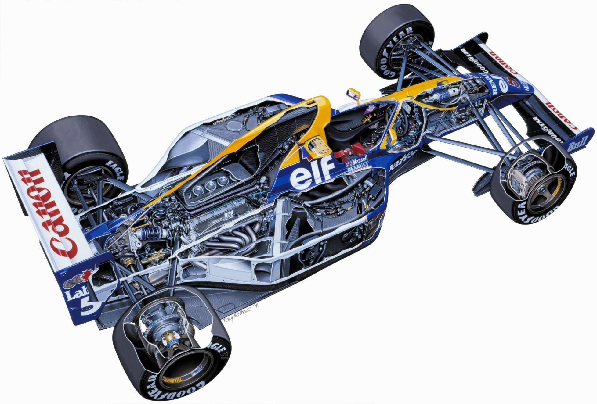
The following image of the 1993 McLaren MP4-8 illustrates this vs the 1991 Williams FW14:
https://www.flickr.com/photos/nealhumphris/5006587581/
Image

The front bodywork regs in 1990 were similar to 1988, but for 1991 the front bodywork minimum height was raised by 25mm and I think this must have only applied to bodywork ahead of the front wheel centreline, enabling the designers to place the front wing extensions behind that point on the reference plane.
The regs also stated that under no circumstances could bodywork be placed below the reference plane, however we know titanium skid blocks were fitted, but there was no separate provision for this installation to mitigate the ref plane height limit. I can only surmise that the designers capitalised on the +/- 5mm tolerance allowed across the surface of the flat bottom.
bhall II wrote:Frankly, your guess is as good as mine here. I can see them as turning vanes that directed wheel wake away from the floor, because...
Honda R&D Technical Review 2009 wrote:When the vehicle is cornering, accelerating, or decelerating, the tires are constantly deformed due to vertical, lateral, and longitudinal forces.

[Methodology of study, which included acquisition of real-world track data that showed a side force of 9000 N caused the tire's contact patch to deform by 20mm]

The measured front tire shape was analyzed using CFD. This analysis showed that, in comparison to a tire with no side force acting on it, approximately 5% of the vehicle’s downforce was lost when a side force of 9000 N acted on the tire.

Figure 17 shows the total pressure distribution close to the road surface with and without a side force acting on the tire. The results show that the position of the separation point on the outboard-side wall of the tire moves back significantly when a side force acts on the tire. This backwards shift of the separation point changes the circulation around the tire in the XY planes, and the tire wake which previously flowed to the outboard of the vehicle now flows under the vehicle.

The fact that this reduces the dynamic pressure underneath the vehicle, resulting in a decline in downforce, can be seen from the change in the static pressure underneath the vehicle when the tire goes from a state of no side force to one in which side force is acting.

[...]

http://i.imgur.com/8ZQkKCE.jpg
...and I can also see them as turning vanes that managed tip vortices in order to create more downforce at the rear of the car via strengthened edge vortices in the diffuser:

http://i.imgur.com/6SaK6nf.jpg

http://i.imgur.com/nvsRT2y.jpg

http://i.imgur.com/BIet568.jpg

Of course, those two ideas aren't necessarily mutually exclusive. But, who knows?
Some great info there bhall, thanks.

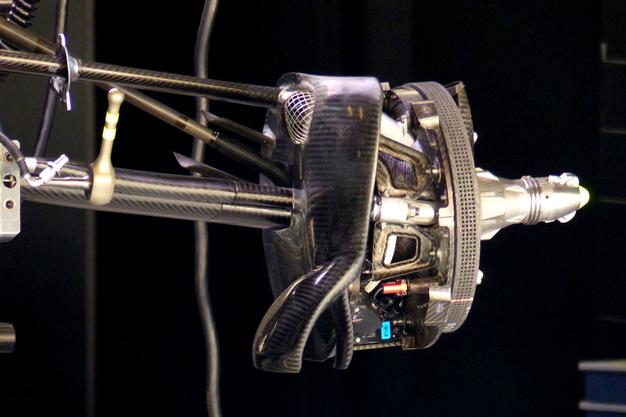
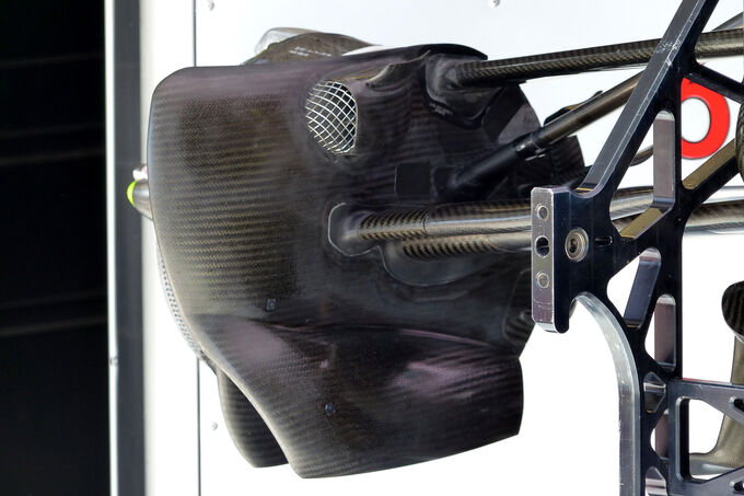
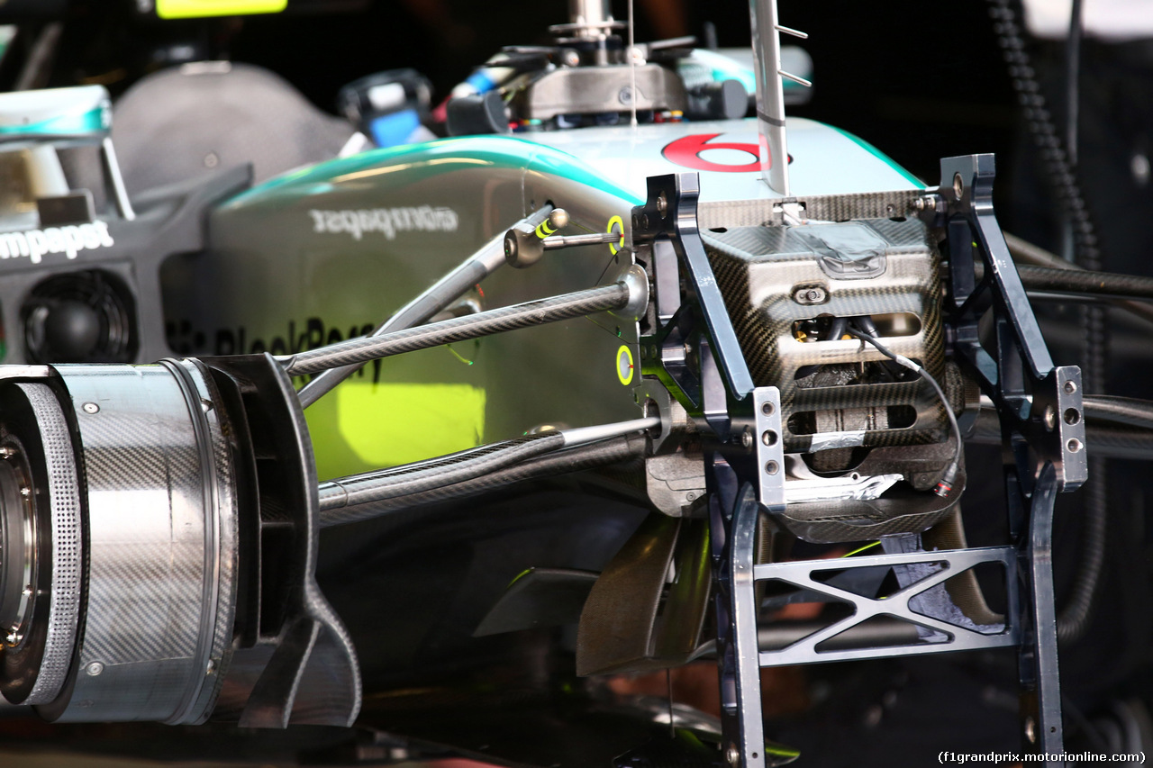
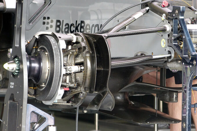
I wonder if the following vanes inboard at the bottom of the W06's front brake duct assembly serve a similar purpose?:
Image
Image
Image
Image
Image

OO7
OO7
171
Joined: 06 Apr 2010, 17:49

Re: 1991 & 1992 F1 Front Wing Regulations

Post

andylaurence wrote:
bhall II wrote: Frankly, your guess is as good as mine here. I can see them as turning vanes that directed wheel wake away from the floor, because...
At the Willem Toet lecture last month, he touched on the endplate extensions that ran inside the front wheels. They were deleted in 1994 after Senna's death. He was at Benetton at the time and stated a loss of something like 20% (I forget exactly, but it was substantial). They were used to guide wheel wake outboard of the car and avoid the floor/diffuser.
Great Info Andy! After comments from you and bhall I decided to pull out an old book I haven't looked at in many years:
Image
The idea of using vortices to seal the sides of the car stemmed from my memory of this book. Having looked at it again the author seems to suggest that the concept was applied to early CART cars, after the banning of sliding skirts. The 1991 Jordan 191 is the only car I can recall that has side pods shaped in a fashion similar to the profiled side pod McBeath illustrates. That illustration however shows the vortex rotating in the opposite direction to the one bhall illustrated and the rotation occurs along the outside of the side pods:
Image

The cut outs on sides along the rear floor could serve as the entrance into the diffuser as bhall illustrated:
Image

I wonder if this technique was seldom used on single seaters and instead became the preserve of Group C and IMSA sportcars, utilising diveplanes to create powerful vortices along the sides of the cars?:
http://www.mulsannescorner.com/nissangtpzx-t-5.html

bhall II
bhall II
473
Joined: 19 Jun 2014, 20:15

Re: 1991 & 1992 F1 Front Wing Regulations

Post

Depending on the degree of continuity in the regulations between 91-92 and 1994, this might be the answer...
1994 Technical Regulations wrote: 3.2 Width ahead of the front wheel centre line:

The bodywork ahead of the front wheel centre line is limited to a maximum width of 140cm. Nevertheless, any part of the bodywork ahead of the front wheel centre line exceeding [an] overall width of 110cm must not extend above the height of the front wheel rims with the driver aboard seated normally and irrespective of the fuel load.

3.3 Width and shape between the front and rear wheels:

The maximum width of the bodywork behind the centre line of the front wheels and in front of the centre line of the rear wheels is 140cm.

Between the rear edge of the complete front wheels and the front edge of the complete rear wheels all sprung parts of the car visible from directly beneath the car must lie on one plane. All these parts must produce a uniform, solid, hard, rigid (no degree of freedom in relation to the body/chassis unit), impervious surface, under all circumstances. The periphery of the surface formed by these parts may be curved upwards with a maximum radius of 5cm.

[...]

6 Height:

Except for the rollover structures, no part of the car can be higher than 100cm from the ground. However, any part of the rollover structures more than 100cm from the ground must not be shaped to have a significant aerodynamic influence on the performance of the car. Furthermore, any part of the car behind the centre line of the rear wheels must not be more than 95cm from the ground.

All height measurements will be taken with the car in normal racing trim with the driver aboard seated normally.
To be continued...