2 stroke thread (with occasional F1 relevance!)

All that has to do with the power train, gearbox, clutch, fuels and lubricants, etc. Generally the mechanical side of Formula One.
J.A.W.
109
Joined: 01 Sep 2014, 05:10
Location: Altair IV.

Re: 2 stroke thread (with occasional F1 relevance!)

Post

Here's some interesting gas-flow tech: http://www.chengfluid.com/flow_conditioner/

Click on 'LAD' ( large angle diffuser) - it appears this design would enable much more compact tuned pipes for 2Ts.
"Well, we knocked the bastard off!"

Ed Hilary on being 1st to top Mt Everest,
(& 1st to do a surface traverse across Antarctica,
in good Kiwi style - riding a Massey Ferguson farm
tractor - with a few extemporised mod's to hack the task).

J.A.W.
109
Joined: 01 Sep 2014, 05:10
Location: Altair IV.

Re: 2 stroke thread (with occasional F1 relevance!)

Post

Muniix wrote: You seem to be completely forgetting how one would approach the design of an engine with a Bishop Rotary valve.
Given the extensive knowledge gained during the CFD analysis of the BRV, the windows will be the full length of the bore minus a few mm, and the width will be determined by flow requirements for the engines operating range. The flow coefficient is the important issue, it is not just port area.
One would have again done some CFD to optomise this. But essentially is depends on the flow coefficient through the window and the valve as a whole, that is why the BRV has the throat to increase the pressure to avoid seperations as it turns around to flow into the cylinder.

Something that has never been done on your rotary valve, If I were you I'd be setting up Stanfords SU2 cfd code and doing some optimisation, You really need to work out how to get the air flow turned into the cylinder through your valve without restricting it. Some streamlines and a real idea of what the flow will actually look like, and its coefficient. Bishop valves actually flow better in higher bsr engines at equal cc's.

A couple of pages back, Manolis posted an interesting hi-tech 'clean/green' 2T design from: http://www.primavis.eu/about

Baldini's patent also includes a triple cylinder 2T design which not only features rotary drum inlet & exhaust valves,
but also appears to utilize the 3 cylinder block in a synergistic flow scheme, rather than as 3 discrete units, in line.

See Fig. 12 in this patent drawing set: http://www.google.tl/patents/US20120304972
"Well, we knocked the bastard off!"

Ed Hilary on being 1st to top Mt Everest,
(& 1st to do a surface traverse across Antarctica,
in good Kiwi style - riding a Massey Ferguson farm
tractor - with a few extemporised mod's to hack the task).

Tommy Cookers
620
Joined: 17 Feb 2012, 16:55

Re: 2 stroke thread (with occasional F1 relevance!)

Post

J.A.W. wrote:Here's some interesting gas-flow tech: http://www.chengfluid.com/flow_conditioner/
Click on 'LAD' ( large angle diffuser) - it appears this design would enable much more compact tuned pipes for 2Ts.
tuned pipes require inconvenient path lengths because the path lengths determine the time taken for each stage of the 'tuned exhaust' pressure cycle
so there's no scope for shortening the exhaust system

J.A.W.
109
Joined: 01 Sep 2014, 05:10
Location: Altair IV.

Re: 2 stroke thread (with occasional F1 relevance!)

Post

Tommy Cookers wrote:
J.A.W. wrote:Here's some interesting gas-flow tech: http://www.chengfluid.com/flow_conditioner/
Click on 'LAD' ( large angle diffuser) - it appears this design would enable much more compact tuned pipes for 2Ts.
tuned pipes require inconvenient path lengths because the path lengths determine the time taken for each stage of the 'tuned exhaust' pressure cycle
so there's no scope for shortening the exhaust system

Evidently T-C, you haven't read the linked data..
..since in the 'LAD' section - it explains the pipe diffuser angle - flow parameters.

"Proof of the pudding" per an empirical test - must apply though, of course...
"Well, we knocked the bastard off!"

Ed Hilary on being 1st to top Mt Everest,
(& 1st to do a surface traverse across Antarctica,
in good Kiwi style - riding a Massey Ferguson farm
tractor - with a few extemporised mod's to hack the task).

J.A.W.
109
Joined: 01 Sep 2014, 05:10
Location: Altair IV.

Re: 2 stroke thread (with occasional F1 relevance!)

Post

This current 2T research project into 'clean,green' DI developments gives some useful data..

http://www.mtukrc.org/download/idaho/id ... r_2016.pdf
"Well, we knocked the bastard off!"

Ed Hilary on being 1st to top Mt Everest,
(& 1st to do a surface traverse across Antarctica,
in good Kiwi style - riding a Massey Ferguson farm
tractor - with a few extemporised mod's to hack the task).

Muniix
14
Joined: 29 Nov 2016, 13:29
Location: Sydney, Australia

Re: 2 stroke thread (with occasional F1 relevance!)

Post

J.A.W. wrote:This current 2T research project into 'clean,green' DI developments gives some useful data..

http://www.mtukrc.org/download/idaho/id ... r_2016.pdf
Some interresting idea may be to use the Mahle Jet Ignition, should work on both two stroke and four, it just needs the right pressure action to exhange the gasses between pre and main chambers. Of note the Mahle TJI was developed by Oz engineer Dr. William Attard here is Oz for some time and then completed at Mahle powertrain in the UK. He also worked at Bishop on the rotary valve, the person who did the CFD on the Bishop now works at Memjet creators of the worlds fastest colour inkjet printer (one a4 page / second) he was also the first to successfully model tumble breakdown to turbulence showing the energy cascade theory. The advantage of the TJI is its ultra lean combustion at lambda's up to 1.85 with no loss of bmep and sustains combustion to 2.1 and 2.35 with liquid petroleum gas, has a thermal efficiency up to 46% thou that includes pumping improvements through reduced intake throttling due to increased intake volume, one paper quotes ~38%.

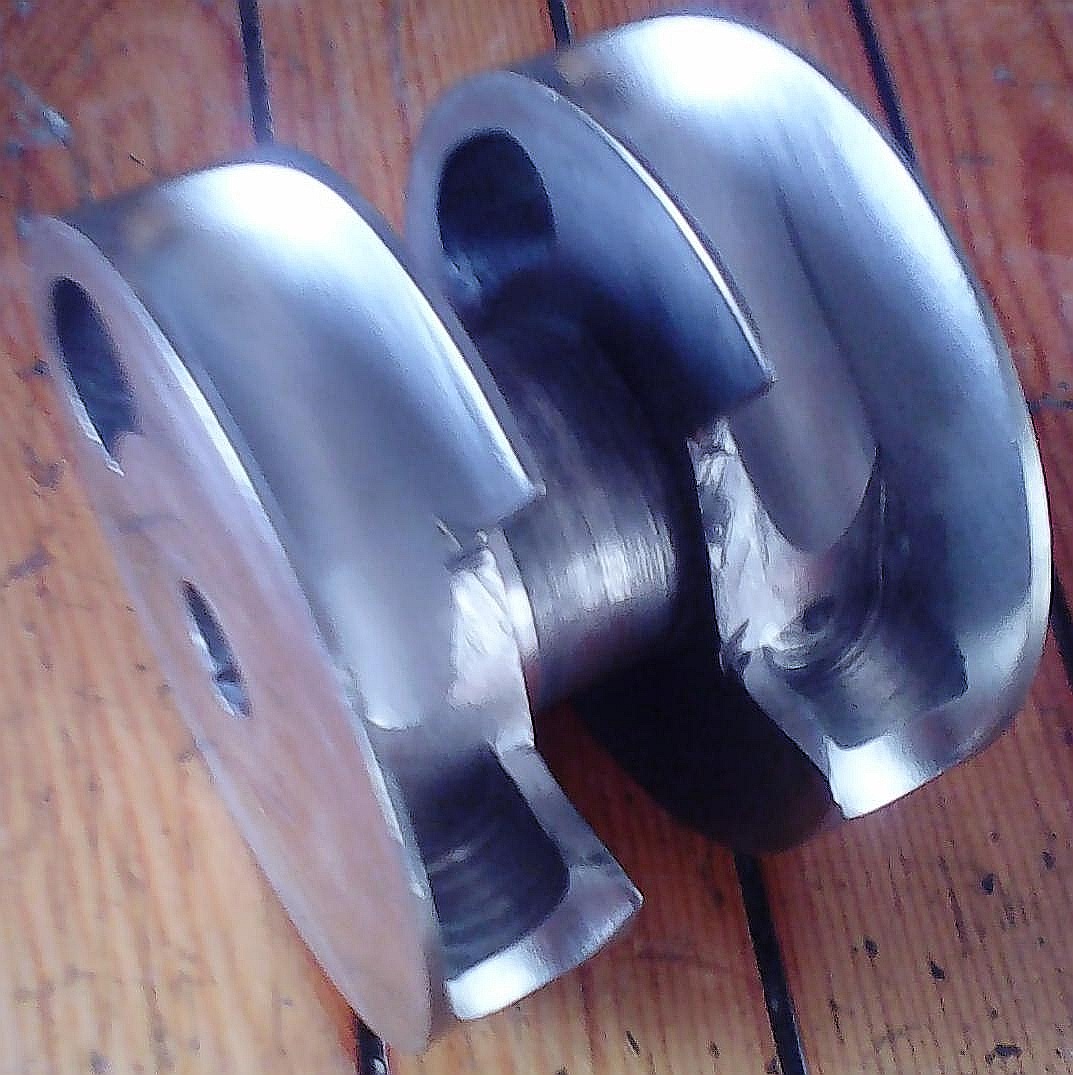
Another bottom end of note is the BMR Suzuki supermono that won the 1998 championship with a female rider, beat the Ducati supermono's. It has an interesting piston motion, tdc is at 19.4 atdc and bdc is at 208.6 so tdc of the big end and piston are different. Ideas on how this would effect inertial torque behaviour. I've written some ruby code to model piston motion using TDD with hand calculated numbers in the tests, still not sure i have it correct thou. It mechanism does have features that would work well with TJI, the extra time after piston tdc with the increased oxygen left from ultra lean, could allow direct injection to support further combustion, constant pressure combustion. With the increased crank duration to blow down exhaust gas pressure(4T), the reduced crank duration on bdc to tdc of ~170 degrees.

replying at 1am, likely makes my text a little hard to follow.
I'll leave it at that atm.

Image

Tommy Cookers
620
Joined: 17 Feb 2012, 16:55

Re: 2 stroke thread (with occasional F1 relevance!)

Post

background to the above -
http://www.caferacer.net/forum/general/ ... motor.html
the crankshafts I assume minimise vibration
(the Ducati Supermono's of course nearly cancels inertia torque as well as minimising vibration)

J.A.W.
109
Joined: 01 Sep 2014, 05:10
Location: Altair IV.

Re: 2 stroke thread (with occasional F1 relevance!)

Post

Muniix wrote: Some interesting idea may be to use the Mahle Jet Ignition, should work on both two stroke and four, it just needs the right pressure action to exhange the gasses between pre and main chambers. Of note the Mahle TJI was developed by Oz engineer Dr. William Attard here is Oz for some time and then completed at Mahle powertrain in the UK. He also worked at Bishop on the rotary valve, the person who did the CFD on the Bishop now works at Memjet creators of the worlds fastest colour inkjet printer (one a4 page / second) he was also the first to successfully model tumble breakdown to turbulence showing the energy cascade theory. The advantage of the TJI is its ultra lean combustion at lambda's up to 1.85 with no loss of bmep and sustains combustion to 2.1 and 2.35 with liquid petroleum gas, has a thermal efficiency up to 46% thou that includes pumping improvements through reduced intake throttling due to increased intake volume, one paper quotes ~38%...
Yeah, if of interest, check back to page 66 of this thread, ( 'bout 1/2 down) I linked an Australian ( RMIT) academic paper considering the potential value of 'jet ignition' DI - for 2T use.

I think you'll also find that some 70 odd years ago NACA published research papers demonstrating this on empirical test - what Harry Ricardo had reckoned about sleeve valve flow coefficients - having just such an advantage over poppet valve set-ups - way back then...

& Bristol had a production DI unit ready to go, but was stymied by the gas turbine take-over of larger aero-engines.
"Well, we knocked the bastard off!"

Ed Hilary on being 1st to top Mt Everest,
(& 1st to do a surface traverse across Antarctica,
in good Kiwi style - riding a Massey Ferguson farm
tractor - with a few extemporised mod's to hack the task).

manolis
107
Joined: 18 Mar 2014, 10:00

Re: 2 stroke thread (with occasional F1 relevance!)

Post

Hello Muniix

Sorry for the delay.

You write:
“I've written some ruby code to model piston motion using TDD with hand calculated numbers in the tests, still not sure i have it correct thou. It mechanism does have features that would work well with TJI, the extra time after piston tdc with the increased oxygen left from ultra lean, could allow direct injection to support further combustion, constant pressure combustion. With the increased crank duration to blow down exhaust gas pressure(4T), the reduced crank duration on bdc to tdc of ~170 degrees.”


The piston motion is as in a conventional engine having an extreme offset (wrist pin offset or crankshaft offset).

You can use the http://www.pattakon.com/tempman/offset_wrist_pin.xls excel file to confirm your calculations.

From the photo:

Image

it seems that the offset to be used is about equal to the crank arm. Replace the –15.00 in the M9 cell by 50 (the crank arm) and you have the piston motion profile, the speed and the acceleration of the piston.

The arrangement doesn’t seem to add extra time after the actual TDC.
The motion of the piston about the actual TDC is about the same.
What changes is the stroke of the piston which increases by some 5%.

In comparison the PatOP engine at http://www.pattakon.com/pattakonPatOP.htm


and the OPRE engine at http://www.pattakon.com/pattakonOPRE.htm


do increase the time the piston spend around the Combustion TDC by more than 30%:

Image

(the combustion feels as occurring at some 25% lower revs).


The arrangement of the photo can, as a boxer, be fully balanced (as regards its inertia forces), in a way similar to that used in the following boxer :

Image

The reasoning is simple: the center of gravity of the set of the two pistons of the modified to boxer double-crankshaft-Suzuki performs a pure sinusoidal motion. The set of the balance webs on the two counter-rotating crankshafts performs also a pure sinusoidal motion. Etc. The drawback (in comparison to a conventional boxer) is the uneven firing in case of 4-stroke.

Thanks
Manolis Pattakos

manolis
107
Joined: 18 Mar 2014, 10:00

Re: 2 stroke thread (with occasional F1 relevance!)

Post

Hello Muniix

You write:
“The reduced crank mass, could be helping the bike turn-in and out faster, the effects on front suspension vibration and harmonics effecting grip and acceleration out of the corner.”

The mass of the crankshaft of the Yamaha cross-plane M1/R1 is not less than the mass of the conventional four-in-line.

The counter-rotating balance shaft reduces in a degree the gyroscopic rigidity of the bike, but not much.

Thanks
Manolis Pattakos

J.A.W.
109
Joined: 01 Sep 2014, 05:10
Location: Altair IV.

Re: 2 stroke thread (with occasional F1 relevance!)

Post

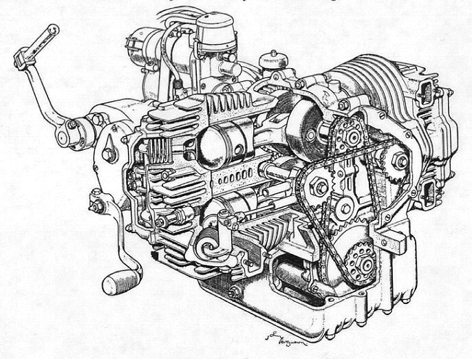
Here is a patent of a twin crank/rod single piston set up: http://www.google.com/patents/US5595147

The inventor was familiar with blade & fork conrods from Harley-Davidson engines ( he did a V-triple version).

AFAIR, the rod angularity proved problematic, even when others tried rods curved like a sabre's blade.
"Well, we knocked the bastard off!"

Ed Hilary on being 1st to top Mt Everest,
(& 1st to do a surface traverse across Antarctica,
in good Kiwi style - riding a Massey Ferguson farm
tractor - with a few extemporised mod's to hack the task).

J.A.W.
109
Joined: 01 Sep 2014, 05:10
Location: Altair IV.

Re: 2 stroke thread (with occasional F1 relevance!)

Post

Still no news of the much hyped Ryger 2T then? & it is after all - now nearly the end of 2016.

So, perhaps just a wee reminder here: http://www.customfighters.com/forums/sh ... ?p=2354521

Manolis may see some features as somehow familiar.. in the internal motion image...
"Well, we knocked the bastard off!"

Ed Hilary on being 1st to top Mt Everest,
(& 1st to do a surface traverse across Antarctica,
in good Kiwi style - riding a Massey Ferguson farm
tractor - with a few extemporised mod's to hack the task).

manolis
107
Joined: 18 Mar 2014, 10:00

Re: 2 stroke thread (with occasional F1 relevance!)

Post

Hello Muniix

You write:
“You seem to be completely forgeting how one would approach the design of an engine with a Bishop Rotary valve.
Given the extensive knowledge gained during the CFD analysis of the BRV, the windows will be the full length of the bore minus a few mm, and the width will be determined by flow requirements for the engines operating range. The flow coefficient is the important issue, it is not just port area.
One would have again done some CFD to optomise this. But essentially is depends on the flow coefficient through the window and the valve as a whole, that is why the BRV has the throat to increase the pressure to avoid seperations as it turns around to flow into the cylinder.
Something that has never been done on your rotary valve, If I were you I'd be setting up Stanfords SU2 cfd code and doing some optimisation, You really need to work out how to get the air flow turned into the cylinder through your valve without restricting it. Some streamlines and a real idea of what the flow will actually look like, and its coefficient. Bishop valves actually flow better in higher bsr engines at equal cc's.”


The CFD analysis is useful, but not a panecea.

Unless I am wrong, according the theoretical analysis of the Bishop rotary valve, their engine would breath freely till 30,000 rpm.
In practice the limit was by far lower (a little more than 20,000rpm).

On this reasoning, the specific CFD analysis was not a successful one.

Nevertheless, the Bishop rotary valve engine proved in practice substantially better, as regards the peak power, than the best poppet valve engines.

Worth to mention: besides the port area and the flow coefficient it is also important the compact shape of the combustion chamber and the central location of the spark plug(s), which are not among the characteristics of the Bishop BRV.

Despite the superiority of the BRV in the F1, it is disappointing that the Bishop rotary valves (which is a version of the Cross rotary valve) was never used in a car or motorcycle.

The PatRoVa:

Image

combines large port area with good coefficient of flow, with compact combustion chamber, with central location of the spark plug and/or injectors, etc.

Thanks
Manolis Pattakos

Muniix
14
Joined: 29 Nov 2016, 13:29
Location: Sydney, Australia

Re: 2 stroke thread (with occasional F1 relevance!)

Post

manolis wrote:Hello Muniix

You write:
“You seem to be completely forgeting how one would approach the design of an engine with a Bishop Rotary valve.
Given the extensive knowledge gained during the CFD analysis of the BRV, the windows will be the full length of the bore minus a few mm, and the width will be determined by flow requirements for the engines operating range. The flow coefficient is the important issue, it is not just port area.
One would have again done some CFD to optomise this. But essentially is depends on the flow coefficient through the window and the valve as a whole, that is why the BRV has the throat to increase the pressure to avoid seperations as it turns around to flow into the cylinder.
Something that has never been done on your rotary valve, If I were you I'd be setting up Stanfords SU2 cfd code and doing some optimisation, You really need to work out how to get the air flow turned into the cylinder through your valve without restricting it. Some streamlines and a real idea of what the flow will actually look like, and its coefficient. Bishop valves actually flow better in higher bsr engines at equal cc's.”


The CFD analysis is useful, but not a panecea.

Unless I am wrong, according the theoretical analysis of the Bishop rotary valve, their engine would breath freely till 30,000 rpm.
In practice the limit was by far lower (a little more than 20,000rpm).

On this reasoning, the specific CFD analysis was not a successful one.

Nevertheless, the Bishop rotary valve engine proved in practice substantially better, as regards the peak power, than the best poppet valve engines.

Worth to mention: besides the port area and the flow coefficient it is also important the compact shape of the combustion chamber and the central location of the spark plug(s), which are not among the characteristics of the Bishop BRV.

Despite the superiority of the BRV in the F1, it is disappointing that the Bishop rotary valves (which is a version of the Cross rotary valve) was never used in a car or motorcycle.

The PatRoVa:

http://www.pattakon.com/PatRoVa/PatRoVa_ports.jpg

combines large port area with good coefficient of flow, with compact combustion chamber, with central location of the spark plug and/or injectors, etc.

Thanks
Manolis Pattakos
The CFD analyses of the BRV showed exactly how it would flow and did flow and the difference was less than 1% to experimental. Nowhere was a rpm of 30,000 mentioned, 20K rpm was the highest. They knew exactly what size valve was needed to support peak torque at a specific rpm. CFD and experimental matched up at speeds they were done at, giving the correct cylinder pressure and flowrate. CFD was very accurate and successfull.

The combustion analyses showed that having the spark plugs where they were, was actaully superior, as the flame kernels would grow to about 8mm then the squish flow would cause them to merge into a 20mm elongated central flame kernal with greater surface area than one plug in the centre would have been. The myth that a central plug is superior is clearly false. Anyway future efforts would be with TJI and it purposefully burns from the outside in to minimise heat loss and other advantages clearly indicated in the research papers.

Muniix
14
Joined: 29 Nov 2016, 13:29
Location: Sydney, Australia

Re: 2 stroke thread (with occasional F1 relevance!)

Post

J.A.W. wrote:Here is a patent of a twin crank/rod single piston set up: http://www.google.com/patents/US5595147

The inventor was familiar with blade & fork conrods from Harley-Davidson engines ( he did a V-triple version).

AFAIR, the rod angularity proved problematic, even when others tried rods curved like a sabre's blade.
Thanks for everything, I've looked at your spreadsheet and put in the changes, one thing i've noticed is it is effectively rotating backwards, which on a normal non offset engine being symetrical at least either side of tdc until the pistons reach half stroke, long before 90 degrees, peak speed is around 77degrees, the con rod is moving away equally in each direction of rotation. I coded to be observing the left crankshaft clockwise starting from tdc.

May be interresting is another Oz engineer Ian Drysdale created a V-twin with rods like a radial to keep cylinders inline, called the godzilla, i'll see if I can include an article I have, (he made a v8 motorbike as well, you likely already know who i'm talking about he imported a whole radial aircraft engine from the US.) Try searching for Drysdale Godzilla.

I'm just going through the motions trying to identify the ideal engine design for the Motoinno TS3 suspension, which has an amazing ability around corners, you can jump on the front brake midcorner and it holds its line, same with full throttle, handles better than a 250 gp bike and makes bumpy corners feel super smooth under brakes, also breaking load holds rear tyre to the ground not lifting the rear, rotating the bike. Likely this would have saved Marco SImoncelli given his accident was caused by the telescopic forkes oscalating on lean loosing grip and then regaining grip as the wheel mass rotated after riding up the circuit edge.

The TS3 reduces the weight, so a multi cylinders engine may not be needed if a high efficiency single could do, and more refined that single can be. So ideally a narrow light short, high efficient engine, a single cylinder Panigale taken to the logical extreme. If more power is needed a Presure wave supercharger could be used to improve efficiency.

The piston motion after tdc is different where on a normal engine the big end is travelling away from cylinder centre axis shortening the rod length, whereas on the twin crank the rod is becoming more vertical, so the piston accelerates away slower rather than faster as is normal, the asymetry is now between tdc- bdc being 192 degrees and 168 back to tdc. Normally the asymetry moves from midstroke positions each side of tdc and bdc as the effective rod length changes. This effects the crank angle cylinde pressure curve and adds a few percent more rotational torque to the crank with same cylinder pressure profile. The crank/rod angle is slighly better.

Your piston speed vs bishop rotary valve seal means speed, assumption pistons have differend peak and mean speed, the brv doesn't. Total Seal say rings experience 40-50 metres/second no issues even when reversing direction and accelerating all the time so a 44 mps constant speed is fine. An 80mm valve can handle 21krpm crank speed ok. It is the bearings that can be the speed issue, An 80mm valve in a 120.65:62.3 mm bore:stroke engine can have a window of 112.65 by 36mm and the flow seems to be good on a SU2 run. Put in dual TJI units, add in lpg direct injection, and optimising the extra crank duration with multiple injections to achieve constant combustion pressure. Not having the combustion volume massive increase as the piston descends opening up the combustion chamber to the full area of the cylinder causing a massive compression ratio drop in a few degrees, given your tight compact compression volume geometry, a huge heat flux release will happen with little work done on the crank and the volume increases.

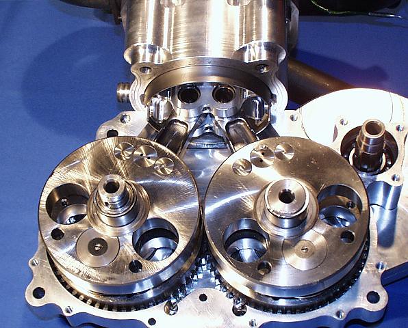
With the PatRoVa, the air streams are facing at each other, the pressure gradients between their windows will hinder each others flow into the cylinder. The are flowing almost directly into each other, this will need some carefull flow optimisation using CFD to identify the flow paths and structure and more importantly the pressure gradients. Given how accurate cfd is now, and the workflow built into SU2 for this specific optimisate task/workflow. Your geometry would be a tricky thou. (I gave it a go, but our mesh god is away now for 8 weeks I'm usually the IT guy optimising the cluster nodes). Maybe offsetting of the window positioning, staggering of the open and close times, shaping of the windows inside the cylinder, to alter their flow paths so they don't interfere with each other, maybe you can engineer in a solution like bishop did, their 'throat' to turn the air flow around and avoid flow seperations as it turned into the cylinder. A throat on the far side to the window entrance, would need the outside of the valve the far side to the window to not rotate. It's a tricky one, 3d flows are tricky effers!

Post Reply