[KVRC ~ish] CCE LMP01

Post here information about your own engineering projects, including but not limited to building your own car or designing a virtual car through CAD.
User avatar
variante
133
Joined: 09 Apr 2012, 11:36
Location: Monza

Re: [KVRC ~ish] CCE LMP01

Post

Hollus, that's supposed to be a Kammback body style, i think. If properly designed, it actually decreases drag. In that case it could also act as a Gurney.

However, having tried that myself on my Magny-Cours car, I couldn't get it to work, so i switched back to a solution similar to the one you've proposed.

User avatar
machin
162
Joined: 25 Nov 2008, 14:45

Re: [KVRC ~ish] CCE LMP01

Post

hollus wrote: Actually, Machin has already suggested a solution to that which doesn't make the expansion in the diffuser even more aggressive:
http://i90.photobucket.com/albums/k248/ ... mjafyv.jpg
I guess the problem for Ric is that he has quite a few things to try now, but general life and time availability just gets in the way... So it is quite difficult to choose which way to go first... I.e. Which change is going to yield the biggest improvement..? One thing is for sure; nobody gets to the top without a lot of time and effort!
COMPETITION CAR ENGINEERING -Home of VIRTUAL STOPWATCH

User avatar
variante
133
Joined: 09 Apr 2012, 11:36
Location: Monza

Re: [KVRC ~ish] CCE LMP01

Post

Machin, my guess is that there's still a transverse pressure gradient at the end of the strake, and the triangular shape is studied to take advantage of that. Basically, that's a secondary vortex generator.

I'm using a similar feature in my car: if you look closely at my diffuser's strake, you'll notice a first and wider stage ending quite early, and a second, smaller one going on up the trailing edge of the diffuser. The first stage takes care of the larger and more powerful vortices that are shed from the leading edge of the diffuser; the problem with those vortices is that they don't follow very well the curvature of the diffuser itself (as well as loosing energy quickly). That's why the second stage exists, shedding much smaller, yet quite effective, vortices.

Now, a further step would be putting all of this together to form a system of vortices. That's why for the third race of the championship I've tried to make all those vortices interact constructively. It looked like a success in my private tests, but it revealed to be failure when the official results came out. Nowadays, until I'll have CFD settings sorted out, I'm using the less elegant version, the one with non interacting vortices.

BTW I could reveal some more details about how vortices used to interact under my old diffuser, if someone is interested.
As promised, some more words (and images) about vortex management under my cars' diffusers.

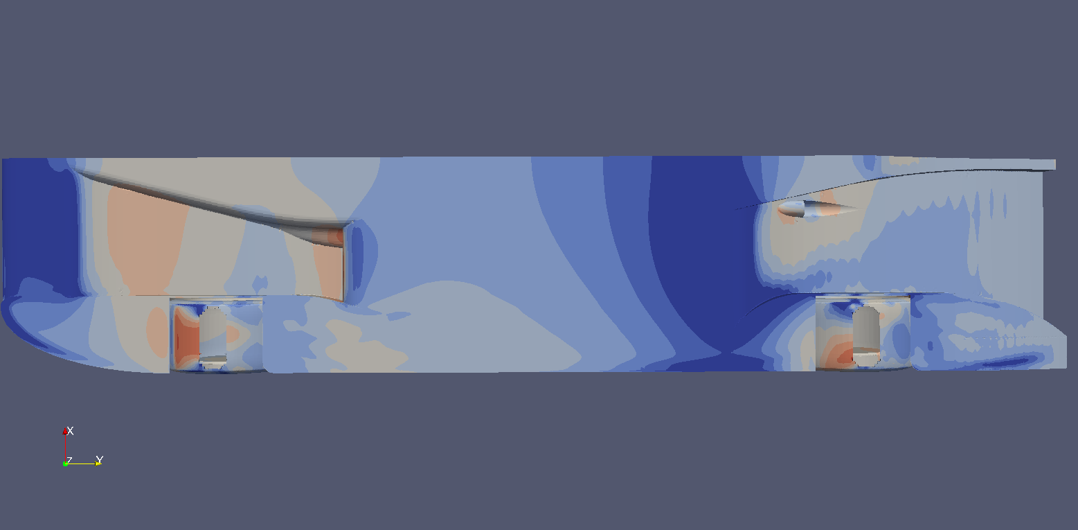
First of all, a comparison between an F1 diffuser without strakes...
Image
...and the same F1 diffuser with strakes:
Image
as you can see, in this case strakes prevent stall and allow for greater sideways expansion.

Now the same comparison with the wingless car that i've used for the Magny-Cours low drag race:
Image
Image
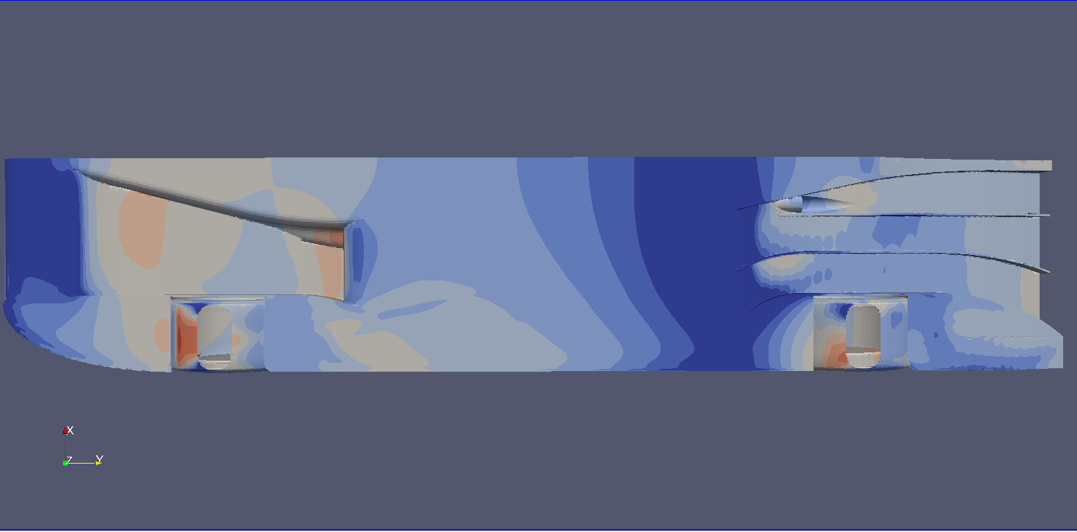
the net downforce gain was 250N (KVRC testing conditions).

Now, the first version of the car featured this configuration:
Image
in this case the strakes do NOT participate actively to vortex generation. On the contrary, they are designed to avoid contact with the primary vortex in order not to disrupt it.
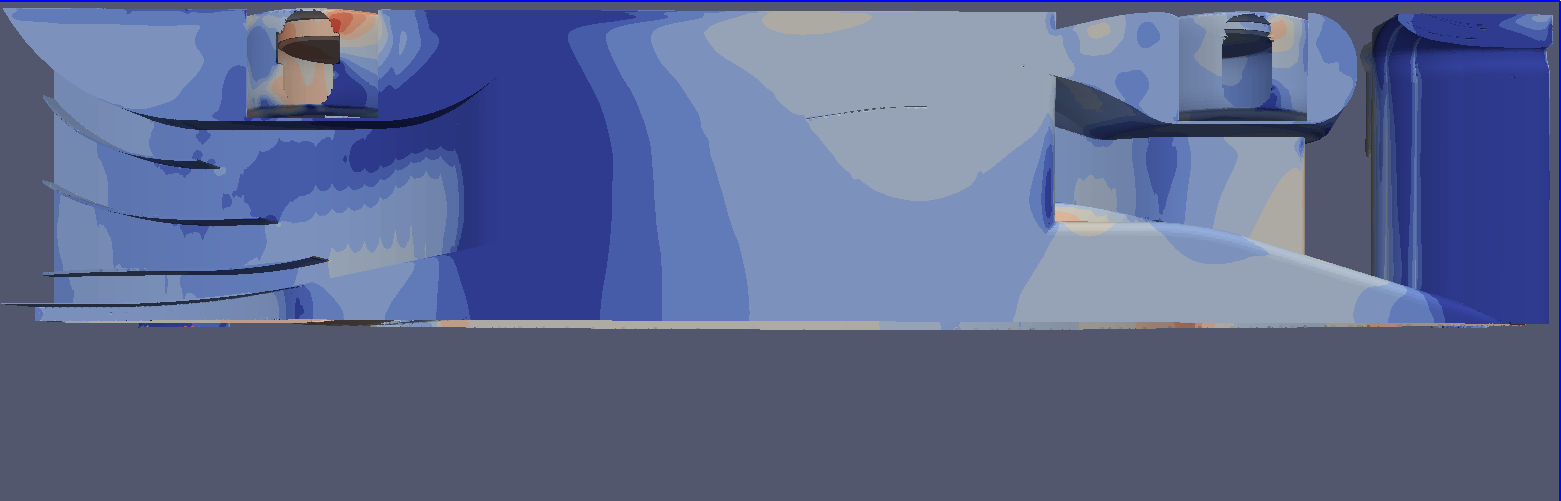
The reason why those strakes are there is to control the flow on the final part of the diffuser, where flow energy is lowest and separation risk is greatest; they simply channel the incoming airflow down the trailing edge in the most “ordered” way, distributing expansion among the whole width of the diffuser.

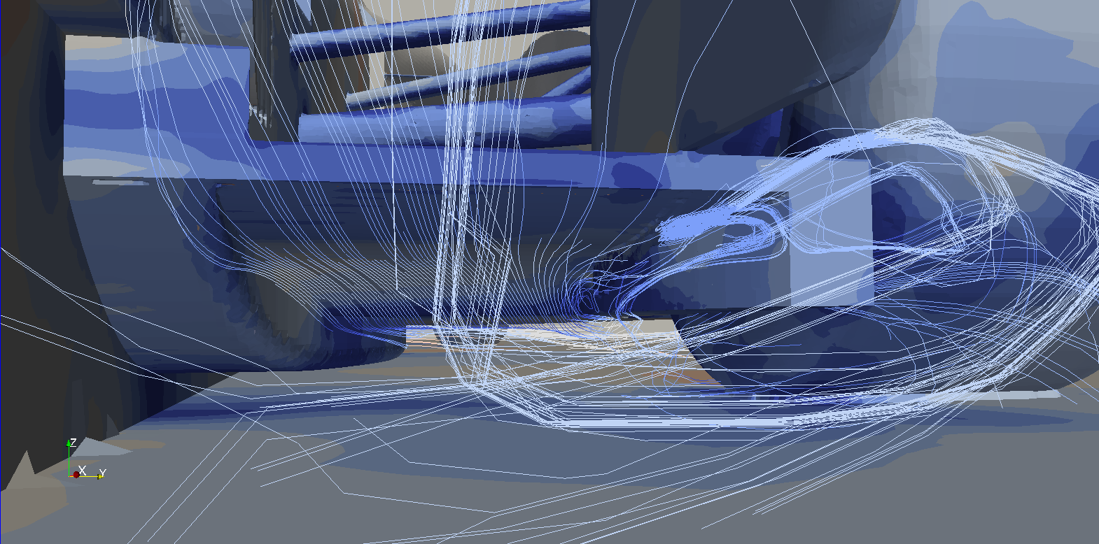
Further developments brought me to a different approach: a solution featuring full lenght and vortex generating strakes. Here you can see an early version of it:
Image
Image
Image
Image
Image
Image
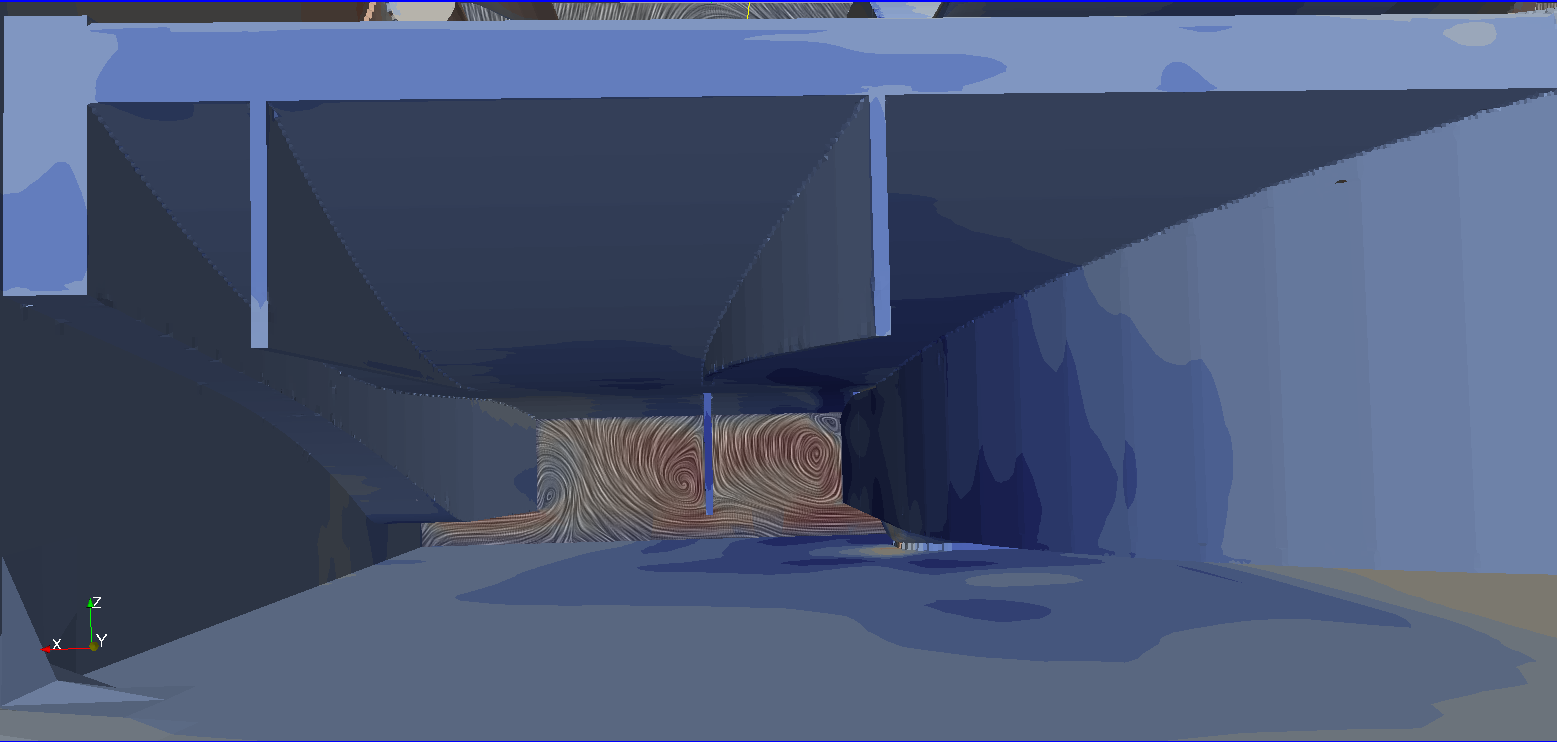
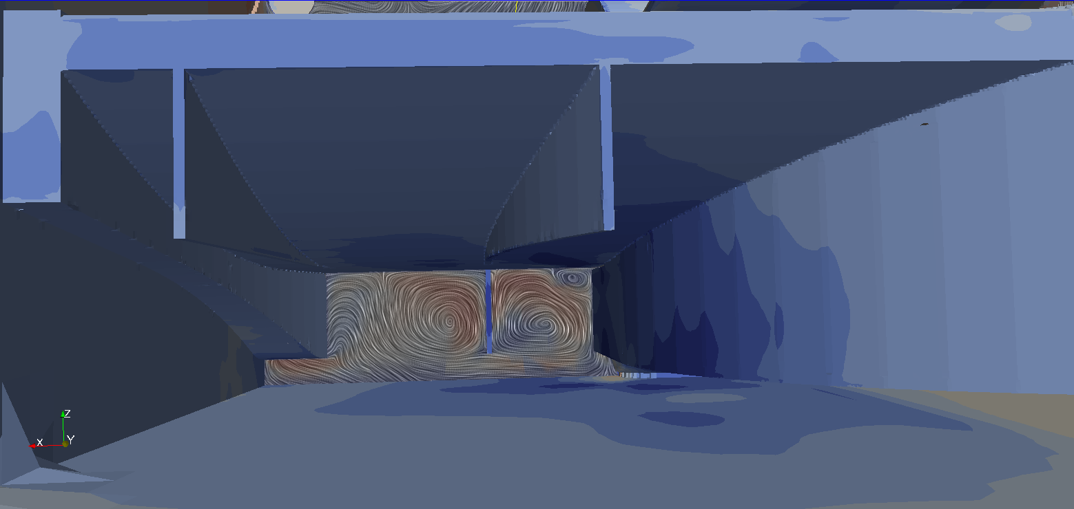
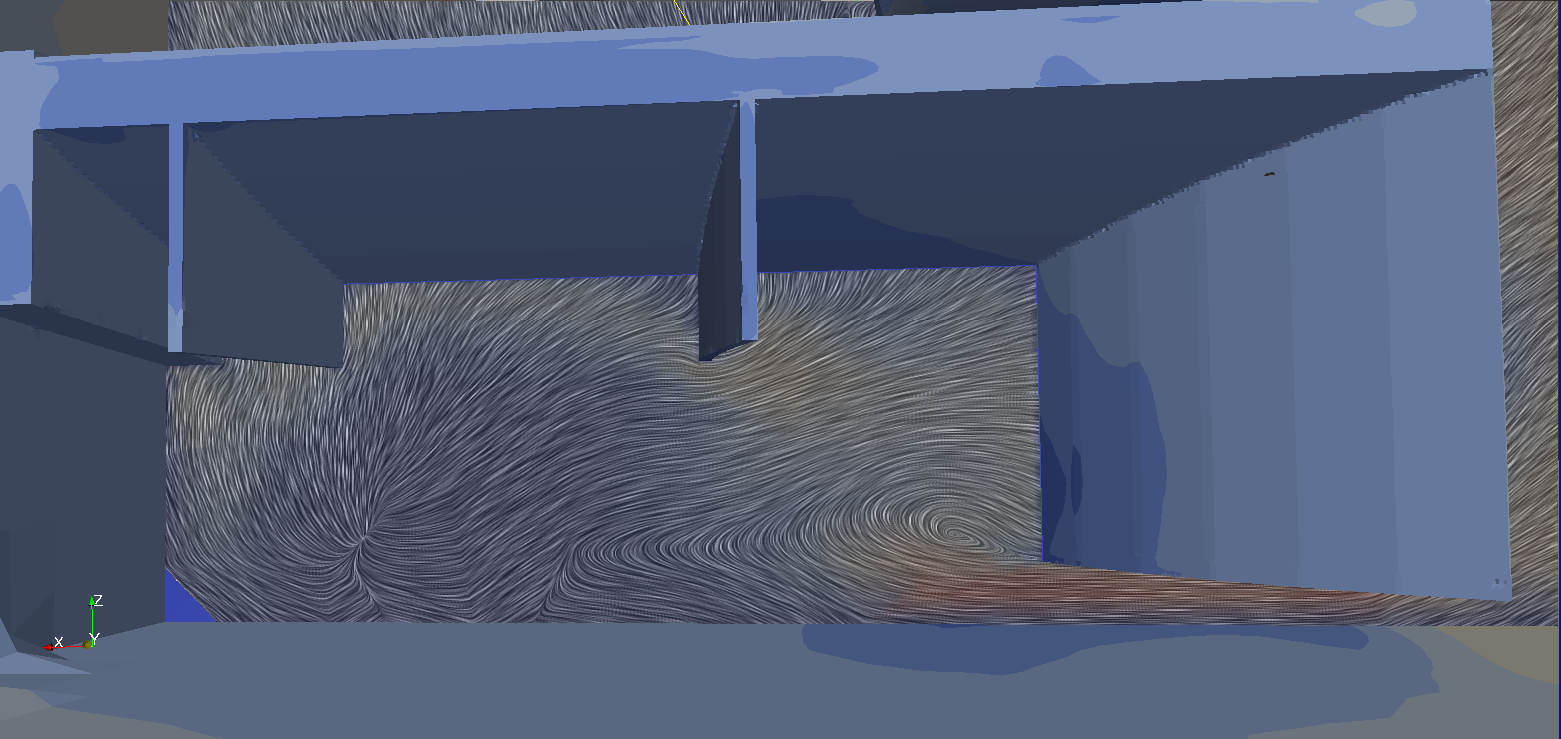
compared to the older version, the new strakes start from the diffuser's throath, generating two primary vortices (instead of a bigger one). This configuration brings the low pressure peak more inwards, exerting more suction under the floor rather than on free stream...
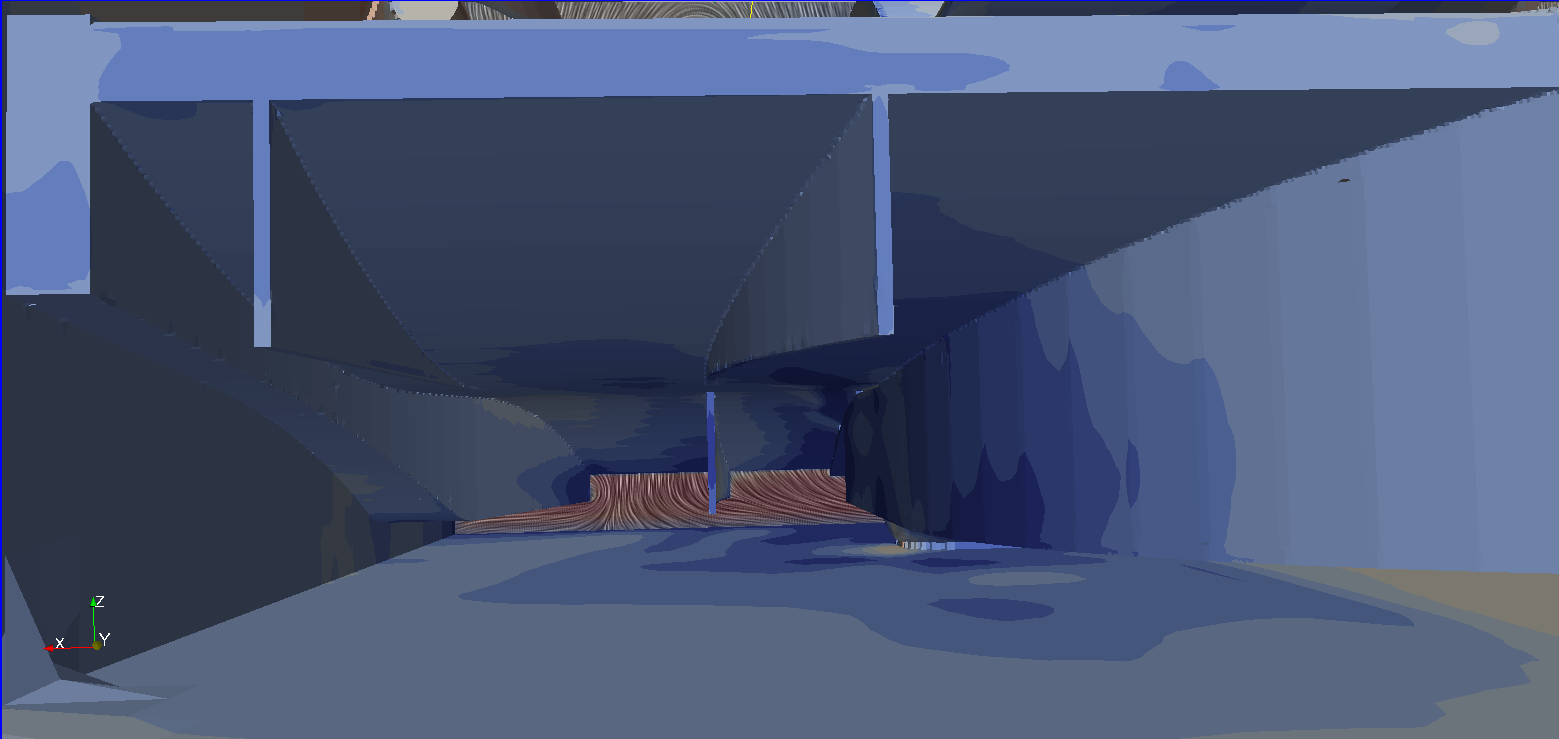
Since this geometry isn't optimized, we can see secondary vorticous formations (luckily stable ones) along the primary vortices.
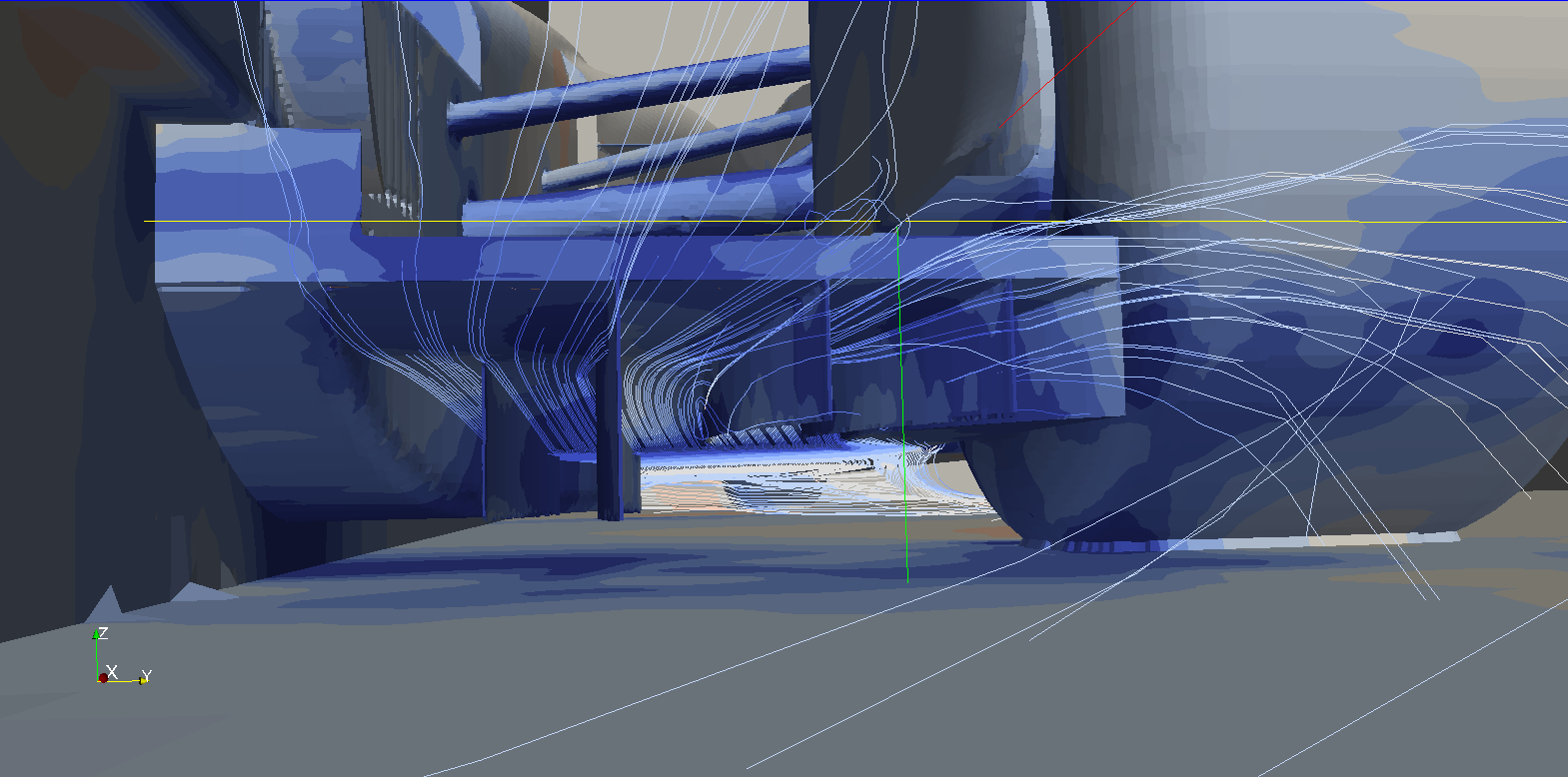
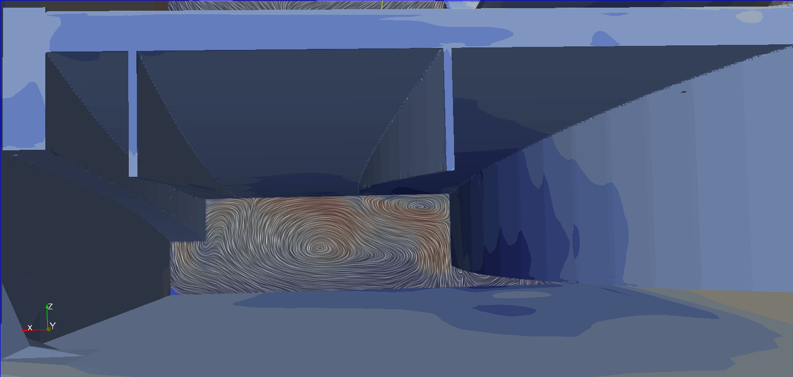
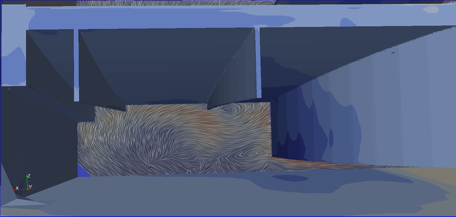
As we approach the second stage of the diffuser, the vortices start loosing energy rapidly, bursting moments later (in another configuration it looked like even more stable vortices couldn't follow the curvature of the diffuser properly). New vortices are required. Because of the primary vortices, the airflow now goes outwards: a new strake takes advantage of this aspect creating a smaller vortex (counter-rotating compared to the previous ones).

The possibilitied offered by such configuration are huge: we could make the primary vortices merge to avoid bursting, create smaller vortices that follow the curvature of the diffuser, use the pressure differential behind the rear tyres,...
I actually tried some of these solutions, with good results (at least with my solver settings...), but i cannot show them yet, for obvious reasons...

Thoughts? Questions?

User avatar
machin
162
Joined: 25 Nov 2008, 14:45

Re: [KVRC ~ish] CCE LMP01

Post

variante wrote:Hollus, that's supposed to be a Kammback body style, i think....
I always thought a Kamm-tail was essentially an aerofoil with the final 3rd 'chopped-off'... Good if you can't fit the full length aerofoil in, and also it can reduce skin friction... They're used for bike frames where the UCI rules allow a maximum 3:1 aspect ratio for frame tubes (the Kamm-tail aerofoil is the 2nd from the right in the image below...

Image

Whereas the swept out internal edge of Ric's wheel fairings had the intention of increasing diffuser volume... I think the CFD suggest it may be too much, and the interaction between the flow from the diffuser and the flow outside the car is a bit messy, which is why I've put that proposal together... The question, though, as I said in the post above: is it better for Ric to do this change... Or something else like the rear wing...?

..decisions...decisions...
COMPETITION CAR ENGINEERING -Home of VIRTUAL STOPWATCH

User avatar
machin
162
Joined: 25 Nov 2008, 14:45

Re: [KVRC ~ish] CCE LMP01

Post

As promised, some more words (and images) about vortex management under my cars' diffusers
Awesome! Will have a read and post questions tomorrow!
COMPETITION CAR ENGINEERING -Home of VIRTUAL STOPWATCH

User avatar
machin
162
Joined: 25 Nov 2008, 14:45

Re: [KVRC ~ish] CCE LMP01

Post

variante wrote:

Now, the first version of the car featured this configuration:
http://i1372.photobucket.com/albums/ag3 ... 1jnel1.png
in this case the strakes do NOT participate actively to vortex generation. On the contrary, they are designed to avoid contact with the primary vortex in order not to disrupt it
Ok... Scrap that... First question... When you say "Primary Vortex" can you indicate on the plan view quoted above where this Primary Vortex starts and what path it takes? Just to be clear....
COMPETITION CAR ENGINEERING -Home of VIRTUAL STOPWATCH

User avatar
variante
133
Joined: 09 Apr 2012, 11:36
Location: Monza

Re: [KVRC ~ish] CCE LMP01

Post

machin wrote:
variante wrote:

Now, the first version of the car featured this configuration:
http://i1372.photobucket.com/albums/ag3 ... 1jnel1.png
in this case the strakes do NOT participate actively to vortex generation. On the contrary, they are designed to avoid contact with the primary vortex in order not to disrupt it
Ok... Scrap that... First question... When you say "Primary Vortex" can you indicate on the plan view quoted above where this Primary Vortex starts and what path it takes? Just to be clear....
It's the big blue strip starting from the throath and bursting about halfway down the diffuser. It follows the outer corner of the diffuser.

User avatar
RicME85
52
Joined: 09 Feb 2012, 13:11
Location: Derby

Re: [KVRC ~ish] CCE LMP01

Post

Great addition to the thread Variante!
Will sink my teeth into that soon.

Definitely lots of ideas to be working on.

Going back to a comment from LDVH, the underside of the front wheel pods were changed the other week but there was an issue with OCCFD diverging and I could work out way as it was such a minor geometry change. CAE suggested changing to the KVRC Stable solution which I did but only after reverting the geometry back to its original state. All tests since have been with the stable solution and no errors have occurred. Now that we have explored the front suspension cover, leading edge of the floor, diffuser and rear wheel pod I can go back and try flattening the under side of the front pod and move on to other suggestions.

User avatar
TalnoRacing
3
Joined: 22 May 2015, 10:50

Re: [KVRC ~ish] CCE LMP01

Post

RicME85 wrote:
TalnoRacing wrote:This has been a very educational thread, thank you to those openly sharing information.

Can someone please advise which Paraview settings are used to generate the image below? I am using version 3.98.0 and I have not been able to generate this type of view.
-Make sure SurfaceLIC is loaded (only need to do this once): go to tools -> manage plugins and expand the "SurfaceLIC" entry. Tick the 'auto load' box. You may need to restart Paraview. If you open the plugin manager again you should now see "Loaded" next to "SurfaceLIC".

-Open the case in Paraview. In the properties panel, tick 'internalMesh' and nothing else in the top panel, and 'U' and 'P' in the bottom panel, then click apply. After it's loaded, you should see a box.

-In the top toolbar, click the 'slice' button and click apply. You can position it before clicking apply, or re-position it later. You should now see a plane, probably coloured by pressure depending on your defaults.

-In the top toolbar, there should be a dropdown displaying "Surface". Change this to "SurfaceLIC". You should hopefully see some streamlines, but they will probably be invalid, all flowing in one direction.

-In the properties panel, look for the "SurfaceLIC: Integrator" subsection. The first element there should be a dropdown called "Vectors". In this dropdown there should be two "U" options with different icons. One of them should show the valid streamlines (the one with the small circular icon).

-At this point you now hopefully have the streamlines. You can play around with the other options in the properties panel, such as "Colour Mode" and "Enhance Contrast" to make it a bit easier to see the colours. You can also re-position the plane (top of the properties panel) to inspect different areas of the car). You can change which scalar field the colours are showing with the other dropdown in the top toolbar - you will probably need to tweak the range by using the range controls in the top toolbar.
Thank you for the clear explanation!

User avatar
RicME85
52
Joined: 09 Feb 2012, 13:11
Location: Derby

Re: [KVRC ~ish] CCE LMP01

Post

Thank Chris, he emailed that to me months ago.

User avatar
machin
162
Joined: 25 Nov 2008, 14:45

Re: [KVRC ~ish] CCE LMP01

Post

variante wrote:in this case the strakes do NOT participate actively to vortex generation. On the contrary, they are designed to avoid contact with the primary vortex in order not to disrupt it.
I was reading an interesting thing about the F18 Hornet aircraft; The sharp Leading edge extension (triangular shape at root wing running forward along the fuselage to a point infront of the canopy) creates a vortex which allows the plane to work at higher angles of attack... However they found that the vortex dissipates about half way along the wing...

Image

So they fitted these little vertical fences (dark grey trapezium shape above the leading edge extension)...

Image

..which enforces the vortex and allows the plane to achieve even greater angles of attack (i.e. better manoeuvrability):

Image

Of course... we're not designing an aeroplane.. but this would appear to be a similar application to your reduced-height diffuser strakes where you're using them to manipulate the main vortex generated further upstream..

..I'm guessing that positioning can be quite critical though and aren't the work of a short moment!
COMPETITION CAR ENGINEERING -Home of VIRTUAL STOPWATCH

User avatar
RicME85
52
Joined: 09 Feb 2012, 13:11
Location: Derby

Re: [KVRC ~ish] CCE LMP01

Post

hollus wrote:
RicME85 wrote: Why does the rear of the car end with a surface perpendicular to the flow?
Its where the exhaust is placed.

User avatar
CAEdevice
47
Joined: 09 Jan 2014, 15:33
Location: Erba, Italy

Re: [KVRC ~ish] CCE LMP01

Post

My contribution to this interesting discussion: this is a section of the results taken at the rear wheels axle. It is a simplified CAD model, so the rear suspension beams are not included.

Image

User avatar
RicME85
52
Joined: 09 Feb 2012, 13:11
Location: Derby

Re: [KVRC ~ish] CCE LMP01

Post

So many pretty swirls :D

I have made tweaks to the car, just about to upload to AWS. I have flattened the underside of the front wheel pod and have implemented a wider throat to the diffuser like JJR.
Yes I know its two changes but Im sure we can see the changes in the results.

MadMatt
MadMatt
125
Joined: 08 Jan 2011, 16:04

Re: [KVRC ~ish] CCE LMP01

Post

I found this picture from Star-CCM interesting:

Image

In their example they also have lift over the front covers!