[KVRC ~ish] CCE LMP01

Post here information about your own engineering projects, including but not limited to building your own car or designing a virtual car through CAD.
User avatar
CAEdevice
47
Joined: 09 Jan 2014, 15:33
Location: Erba, Italy
Contact:

Re: [KVRC ~ish] CCE LMP01

Post

MadMatt wrote:I found this picture from Star-CCM interesting:

http://www.cd-adapco.com/sites/default/ ... k=oPART9MM

In their example they also have lift over the front covers!
It is one of the areas where it is almost impossible to avoid a little lift effect... espcially with the 10mm minimum thickness rules ;)

User avatar
machin
162
Joined: 25 Nov 2008, 14:45

Re: [KVRC ~ish] CCE LMP01

Post

CAEdevice wrote:My contribution to this interesting discussion: this is a section of the results taken at the rear wheels axle. It is a simplified CAD model, so the rear suspension beams are not included.

http://www.caedevice.net/KVRC/SurfaceLIC_01.jpg
That's like a work of art on its own!
COMPETITION CAR ENGINEERING -Home of VIRTUAL STOPWATCH

User avatar
RicME85
52
Joined: 09 Feb 2012, 13:11
Location: Derby
Contact:

Re: [KVRC ~ish] CCE LMP01

Post

RicME85 wrote:New strakes have improved the downforce of the car.
Will post the numbers now and the CFD images later as busy atm.

http://i.imgur.com/5SLGGlG.png

Image
Latest run has flat underside to front wheel pod and a wider throat to the diffuser.
Image

Image

Image

Image


User avatar
LVDH
44
Joined: 31 Mar 2015, 14:23

Re: [KVRC ~ish] CCE LMP01

Post

Looks like a small improvement.
A small feature you could try (it works on my car) is have the side edges of the floor sharp and not rounded.

But the next big thing to work on is your wing. The car is quite balanced. A single element rear wing with similar levels of downforce will have much lower drag. I know I sound like a broken record.

User avatar
machin
162
Joined: 25 Nov 2008, 14:45

Re: [KVRC ~ish] CCE LMP01

Post

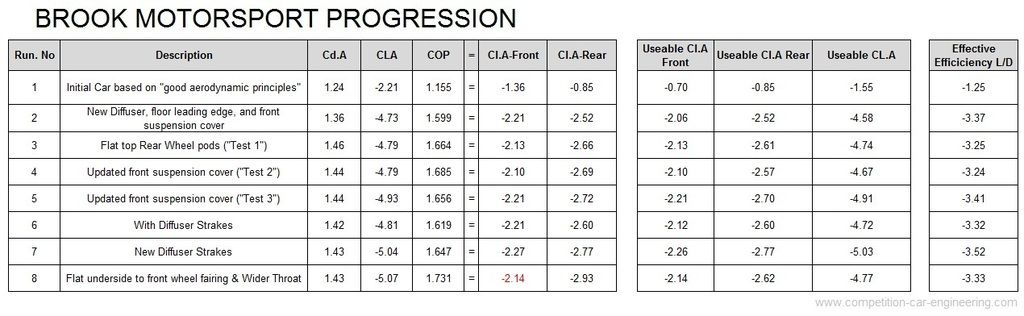
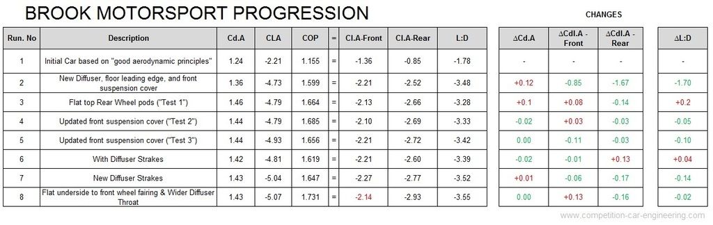
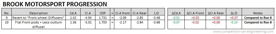
I've said it before... but I quite like to generate Cl.A-front and Cl.A-Rear figures rather than looking at Overall Cl.A and COP: because I think it gives you clearer idea of what is going on... so that's what I've done....

Image

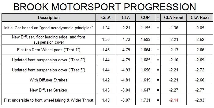
You can see in the table above that the last change has decreased front end downforce compared to the previous iteration, so the COP movement backwards wasn't just as a result of the increased rear downforce... in my eyes this suggests that maybe the "front wheel diffuser" isn't so bad afterall... it is not possible to completely confirm this conclusion from the data provided however, as we don't know if one change is masking the other (e.g. removing the "front wheel diffuser" may have decreased drag, but the wider Diffuser throat might have increased it... or maybe vice versa?!)... all we know is that together those two changes included in the last test resulted in no change to the drag and a little change in balance... I would hazard a guess that this last iteration would actually result in a slower car (I haven't confirmed this on Virtual Stopwatch however) than the previous one ("New Diffuser Strakes")....

However... a change to a single element rear wing, (which produces slightly less overall downforce and hopefully a lot less drag) could redress the balance and make the overall result better than the "New Diffuser Strakes" iteration... !!!!
COMPETITION CAR ENGINEERING -Home of VIRTUAL STOPWATCH

User avatar
machin
162
Joined: 25 Nov 2008, 14:45

Re: [KVRC ~ish] CCE LMP01

Post

Actually... this is worth looking at too... I've shown the "effective" or "useable" Cl.A-front, Cl.A-Rear, Cl.A overall and L:D.. essentially this "gets rid of the COP problem" by ignoring any excess downforce at whichever end of the car has relatively "too much":-

Image

You can see that configuration 8 is actually considerably worse than configuration 7 (actually, it is worse than configuration 2!).. but as per my previous post, maybe overall it could be better if the balance can be re-dressed (by changing the rear wing as LVDH suggests, for example)...

But one thing is for certain: don't submit configuration 8 as it stands!
COMPETITION CAR ENGINEERING -Home of VIRTUAL STOPWATCH


User avatar
machin
162
Joined: 25 Nov 2008, 14:45

Re: [KVRC ~ish] CCE LMP01

Post

One more analysis... My post above might come across as suggesting that the final change wasn't good... however it depends on what your starting position is... if the original car (Run No. 1 in the table below) had had a little more front-end downforce, then the final change (No. 8 ) may have actually brought the car into balance and we would be singing its praises...

For that reason it is worth looking at the coefficient changes that each change brought about, which I present here:

Image

(The conclusion about the entire configuration 8 is still relevant: it is slower than configuration 7, as a result of being less well balanced).
Last edited by machin on 08 Oct 2015, 20:34, edited 1 time in total.
COMPETITION CAR ENGINEERING -Home of VIRTUAL STOPWATCH

User avatar
RicME85
52
Joined: 09 Feb 2012, 13:11
Location: Derby
Contact:

Re: [KVRC ~ish] CCE LMP01

Post

I have two tests running at the moment, one should help figure things out a bit as it is the wider diffuser throat but with the original underside front pod.

User avatar
RicME85
52
Joined: 09 Feb 2012, 13:11
Location: Derby
Contact:

Re: [KVRC ~ish] CCE LMP01

Post

Wider diffuser throat but with the original underside front pod

Image

Image

Image

Image

Machin proposed rear pod - flat front pod, wider diffuser throat

Image

Image

Image

Image

Image

User avatar
machin
162
Joined: 25 Nov 2008, 14:45

Re: [KVRC ~ish] CCE LMP01

Post

Interesting....

Image

Looks like you were definitely right to keep the flat front pods for run 10, as run 9 shows they were actually creating lift at both ends of the car! I presume they were causing some disturbance to the flow which is why they affected both ends ...

Run 10 gained you a nice chunk of efficiency (although downforce was down a bit).... so that was definitely worth doing. I'm wondering if the fact you lost some downforce with this change indicates that there is still potential in the diffuser... i.e. there is another way of getting the downforce back without messing up the flow where it joins the free-stream...? I don't know... and its probably a marginal gain now anyway if we compare your downforce profile to Mantium Ray's... Out of interest it would be nice to see a horizontal flow line slice like you did before; to see the improvement in flow in the diffuser...

..having said that you probably might want to stop divulging all your hard-earned secrets at some point?! I think we have enough raw data now to create a nice "car designers guide" for next year...
COMPETITION CAR ENGINEERING -Home of VIRTUAL STOPWATCH

User avatar
RicME85
52
Joined: 09 Feb 2012, 13:11
Location: Derby
Contact:

Re: [KVRC ~ish] CCE LMP01

Post

Im not fussed about divulging secrets as there are still plenty of things people can do.

Im looking at wing profiles, just doing a very basic test with just the wing and endplates in OCCFD, what do I want to be looking for?
Obviously a reduction in drag is good but what about efficiency? Which numbers specifically show efficiency?

User avatar
machin
162
Joined: 25 Nov 2008, 14:45

Re: [KVRC ~ish] CCE LMP01

Post

Well efficiency is just "Lift divided by drag" (L/D or L:D). But you should set the angle of attack (AoA ) so that the downforce is the same (or roughly the same) with each different wing section you try... If you look back at page 2 of this topic you can see the L:D of that NACA element I posted is around 20:1 at very low angles of attack, but falls to around 12:1 at the sort of AoA you probably should be aiming for... So if you don't test each wing element at the same/similar downforce level then you might be lulled into thinking one element is better when it is actually worse when you put it on your car at the AoA required to balance the car...

Unfortunately it does mean probably multiple runs of the same element to set the AoA to give the same/similar downforce levels... The starting point is your current wing at the current AoA... See how much downforce that gives, and then adjust each element you try until you get the same downforce... Then pick the one with the lowest drag... Sounds simple! :?
COMPETITION CAR ENGINEERING -Home of VIRTUAL STOPWATCH

User avatar
RicME85
52
Joined: 09 Feb 2012, 13:11
Location: Derby
Contact:

Re: [KVRC ~ish] CCE LMP01

Post

Simple enough.
I'm only using the test setting in OCCFD currently to make an incredibly basic assessment then will go to a finer mesh