I am not really convinced by your arguments for the pushrod angle.
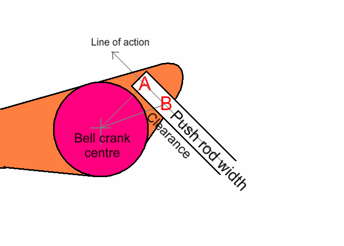
Also the arrangement where the push rod bearing is actually on the active radius(or arc whatever you call it) has less clearance so a you only get a smaller rotation before the push-rod hits up into the bell-crank. This was mostly the reason for me to offset the bearing (but still keeping it on the initial line of action)
Point A is the setup with the bearing right on the effective radius. Imagine the bell crank rotation CCW, there will be a point where the push rod clashes into the pink area. The effective radius also decreases slightly
Ok you say the pushrod will touch the bellcrank more easily when there is a 90° angle.
Solution: You will have to make the bellcrank bigger there is nothing bad about this.
I noticed that both setups will only be at 90 degrees for only one instance in position anyway; as soon as the push rod moves the angle decreases. This is because the arc of the control arm is not the same radius as the bell crank arc. So I focused on keeping it in a small range around 90.
The other advantage is that since B is rotation on a larger radius (not effective radius just the radius to the bearing).. the pusrod stays more vertical and hence the effective radius increases slightly.
Hm.....
Yea the angle slightly changes during movement.
Sounds like you want to make the best out of it and even get an advantage when the angle changes.
I guess you design the car in normal ride height position.
From the picture I say you will get this:
The blue arrow represents the force from the tyre. This force is split up into the green one who acts on a 90° angle on the bellcrank and therefore will be transmitted into the spring. The red one will go into the bearing of the bellcrank and is therefore not loading the spring. It is easy to see that you are currently loosing a significant amount of your force.
Furthermore there is something else happening:
When your pushrod moves up the angle will get closer to 90°. So there is less force lost and more force goes into your spring. This will cause something like a degressive effect of your spring. The more load you get on your tyre the more it will move That is the opposite of what you want.
Normally you would go for a progressive effect.
The more load you have the less the tyre will move.
It is better to start with a 90° layout so the force who gets into the spring will be reduced when the bellcrank rotates.

That is my point of view.
I would like to hear what other people think about this.