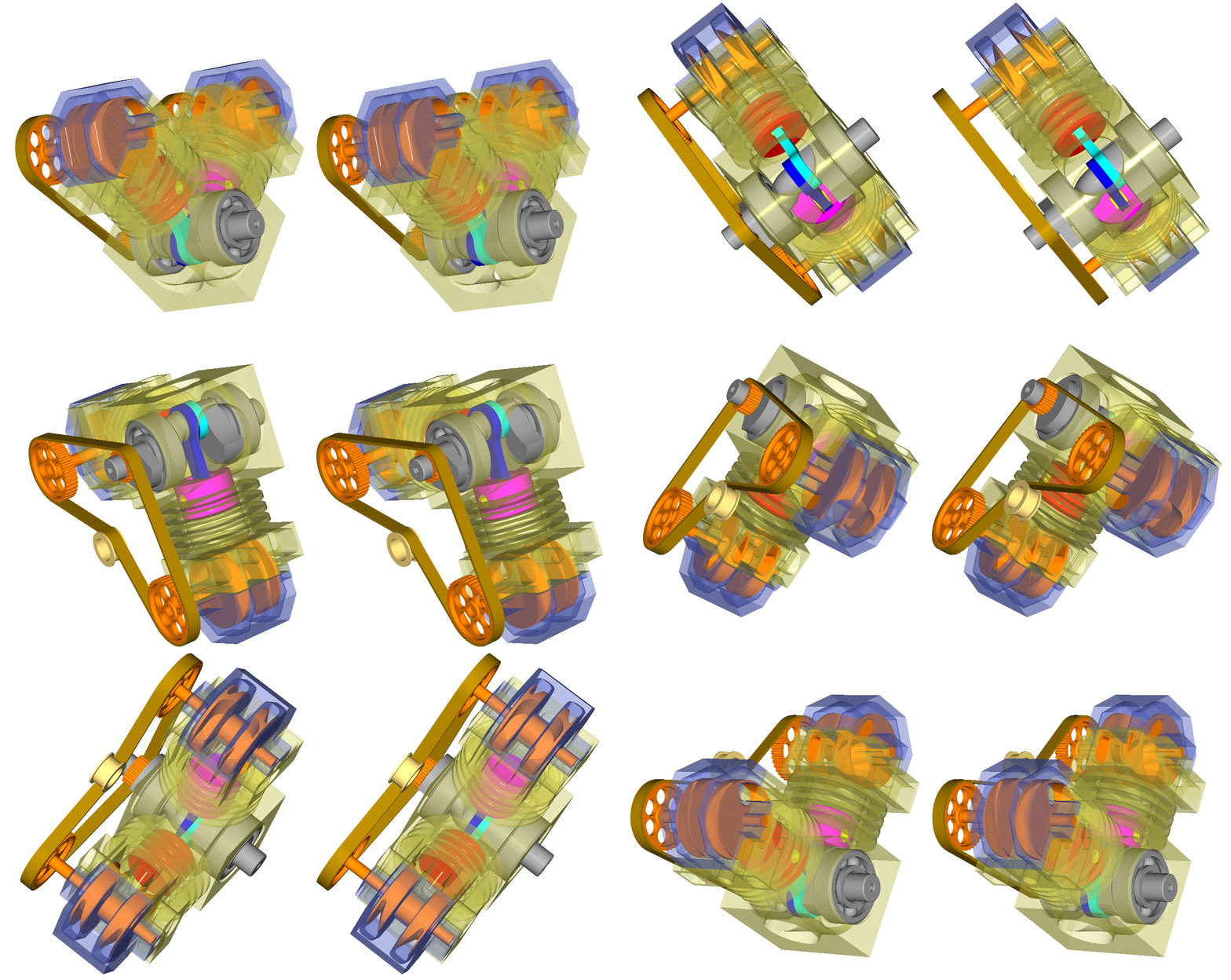
2 stroke thread (with occasional F1 relevance!)

All that has to do with the power train, gearbox, clutch, fuels and lubricants, etc. Generally the mechanical side of Formula One.
manolis
manolis
107
Joined: 18 Mar 2014, 10:00

Re: 2 stroke thread (with occasional F1 relevance!)

Post

Hello Pinger.

You write:
“My interest lies in minimum departure from the typical piston/rod/crank architecture - to minimise mass, avoid untested sealing arrangements, etc.”


In comparison to the unnecessarily complicated Primavis engine, the PatATi engine, which comprises only the typical piston/rod/crank, provides not only asymmetric transfer, but also asymmetric intake without needing neither a reed valve (that, besides adding cost and needing extra space to be mounted, is also putting limitations regarding the reliability and the high revving capacity) nor disc / drum valves.

Thoughts?

Objections?

Thanks
Manolis Pattakos

manolis
manolis
107
Joined: 18 Mar 2014, 10:00

Re: 2 stroke thread (with occasional F1 relevance!)

Post

Hello Pinger.

You write:
“Your explanation M of circumventing friction in your horizontal rotary valve. Are you not creating crevice volume - leading to high UBHC? And, denying the spark plug boss the heat path it requires to cool the plug?”


The added crevice volume is adequately small to cause problems in a 2-stroke, while the problems the rotary valve on the cylinder head solves (no rev limit, no frictional loss, “through scavenging”, asymmetrical timing etc) are by far more significant than the side-effect of the added crevice volume.

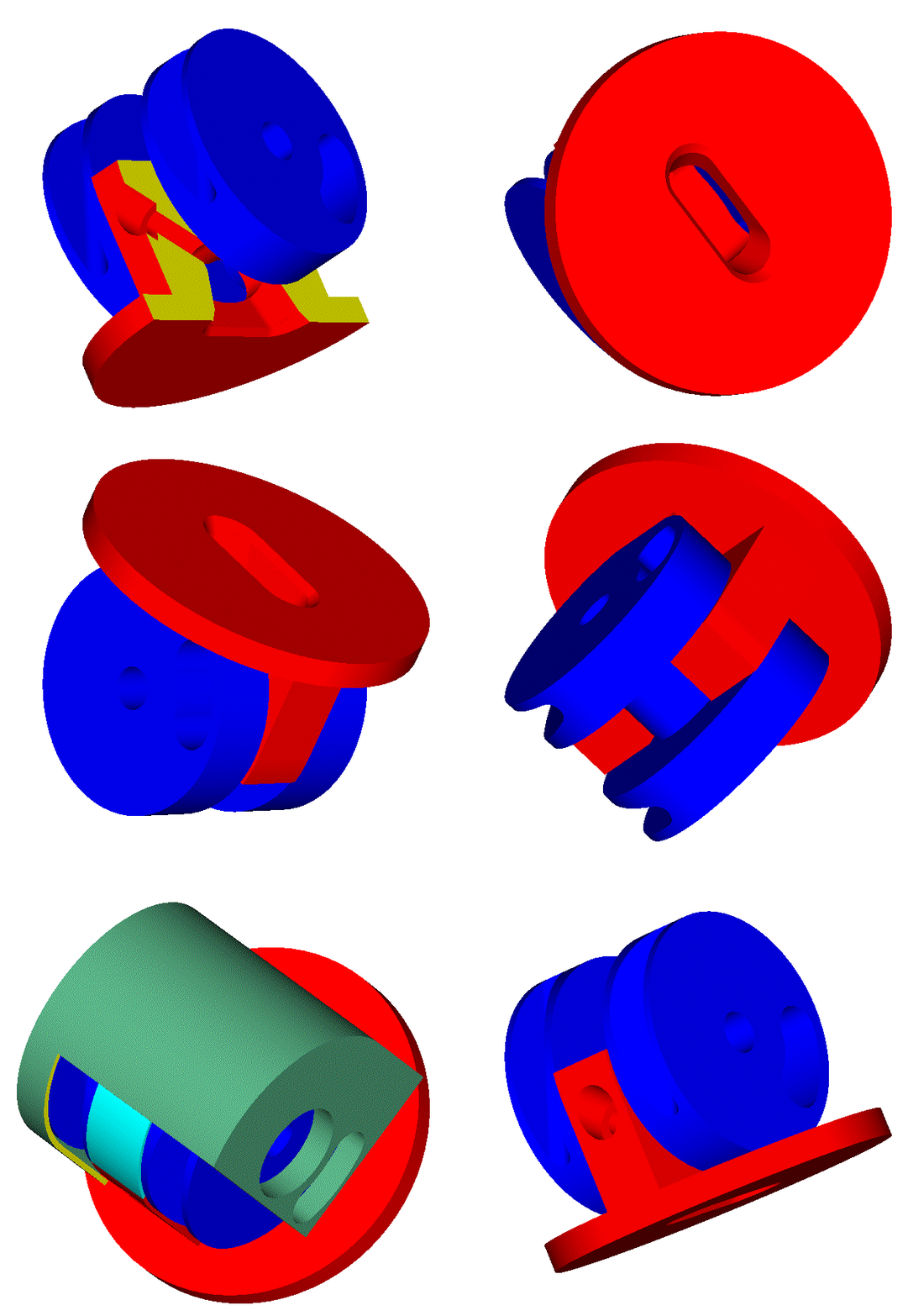
In any case, there is always available the PatRoVa rotary valve with the horizontal rotation axis and the zero crevice volume:

Image


As for the passageway around the spark plug, it may offer a colder spark plug (the thread of the spark plug is not in direct contact with the high temperature part of the cylinder head).

On the other hand, the required passageway is not necessarily at the center of the cylinder.
Alternatively, the passageway can, more easily, be arranged at the periphery of the cylinder / cylinder head, at the other side of the shallow trapezoidal grooves (if it is not obvious, I’ll make a drawing).


Don’t, the 4-stroke sleeve valve Bristol Hercules and Centaurus, have substantially bigger “crevice” volume than the 2-Stroke FlatHead PatRoVa? :

Image

The volume in the “intake-exhaust port” is not exactly a “crevice” volume, but it makes the same damage:
The “intake-exhaust port” on the sleeve is full, during the end of the intake, with fresh air-fuel mixture. At the end of the expansion the same port is used for the exhaust. Any air-fuel mixture in there, goes to the exhaust.

Thanks
Manolis Pattakos

Pinger
Pinger
9
Joined: 13 Apr 2017, 17:28

Re: 2 stroke thread (with occasional F1 relevance!)

Post

manolis wrote:
23 Apr 2017, 12:00
Hello Pinger.

You write:
“My interest lies in minimum departure from the typical piston/rod/crank architecture - to minimise mass, avoid untested sealing arrangements, etc.”


In comparison to the unnecessarily complicated Primavis engine, the PatATi engine, which comprises only the typical piston/rod/crank, provides not only asymmetric transfer, but also asymmetric intake without needing neither a reed valve (that, besides adding cost and needing extra space to be mounted, is also putting limitations regarding the reliability and the high revving capacity) nor disc / drum valves.

Thoughts?

Objections?

Thanks
Manolis Pattakos
Nothing against your set-up. Just that I can achieve asymmetric transfer timing with a conventional piston and rod. Simplicity is all to me!

RE crevice volume. Depends what certification you seek. Bristol obviously didn't have current motoring emission regs in mind. I do. And reducing crevice volume to a minimum is highly desirable if not absolutely essential.

manolis
manolis
107
Joined: 18 Mar 2014, 10:00

Re: 2 stroke thread (with occasional F1 relevance!)

Post

Hello Munnix:

You write:

“Using gas pressure via gas ports is never "at the same time" and why this method is never used as the primary means, it is used as a secondary means as it takes some time for the pressure to build up, like charging a capacitor, it also takes time to discharge.
Case in point - piston rings, their tension performs the seal and gas pressure used to assist only.
This gas porting increases crevice volume and loss of cylinder pressure, creates additional heat that needs to be removed.
. . .
The F1 bishop engine had ultra thin 3mm needle roller bearing of only 10mm width, these worked fine in endurance testing. Even surviving when the 'normal' f1 rods broke when running at MBT ignition timing low 30s btdc due to the fast combustion, fatigue eventually caused the rod to fail, they learned timing needed to be retarded slightly from mbt.”


The typical 4-stroke and 2-stroke PatRoVa design is not adding crevice volume, at all.


The FlatHead 2-stroke PatRoVa does add some small crevice volume, which is a disadvantage, a side effect.
With small volume of the shallow groove above the 2Stroke FlatHead PatRoVa, the pressure need not time to built up (the pressure in the combustion chamber increases progressively, not explosively).


Despite the added crevice volume, I think that if Ralph Watson had thought this “solution” of his problem when he was trying, unsuccessfully, to make his first prototype Aspin engine to operate (read his article at http://ralphwatson.scienceontheweb.net/rotary.html ) , he would be more than happy.


Let’s suppose the added crevice volume in the FlatHead 2-stroke PatRoVa is a big issue.


Doesn’t the 4-stroke Bishop rotary valve add crevice volume, too?

It does (the volume between the rotary valve, the cylinder head and the seals of the window at the top of the cylinder).

But this is nothing as compared to the parasitic “volumes” created around the Bishop rotary valve and cause more serious problems than the increased crevice volume.


The necessarily large clearance between the cylinder head and the valve is the main cause of the problem:

Put two “ultra thin 3mm needle roller bearing of only 10mm width” at some 130mm distance from each other, and support on them a thin-walled pipe (the Cross-Bishop rotary valve) having heavily asymmetrical structure with long / wide cuts (the ports) at its periphery, with an oblique separator at its middle and with highly asymmetric temperature distribution along and around the “pipe” (the one needle roller bearing works cold, the other has needles rolling on the red-hot “exhaust” side of the rotary valve, because the exhaust pipe is the inner ring of this needle roller bearing).

Then put a force of a couple of tons (20,000N) to press the middle part of the lower side of the pipe upwards, and you have the complete scene / picture.

The sealing means of the Bishop can follow the resulting distortion / bending of the pipe-like valve and can keep the high pressure gas into the cylinder.

However, the previously mentioned “characteristics” and “facts” call for “increased radial clearances”, and this is not good, at all.


Don’t believe me, believe the guys of the Bishop Team:


QUOTE from the US7,621,249 patent,
Assignee: Bishop Innovation Limited,
Inventors: Wallis and Thomas:


“The purpose of the present invention is to provide a mechanism that minimises the flow of gas from one port to another, and in particular during those portions of the cycle where there is a large pressure difference between the ports and where the resulting flows will create problems with the operation of the engine.

A typical example of where this is issue occurs is in high performance engines under full throttle. Because of the nature of these engines, they require larger radial clearances and are therefore more susceptible to adverse pressure drops between the ports. Under full throttle operation shortly after the exhaust port first opens the pressure in the exhaust port rises rapidly to well over 1 bar gauge. In arrangements like those in U.S. Pat. No. 4,852,532 (Bishop) this will result in the exhaust being pushed into the inlet port and a consequent loss of performance. Later in the cycle when the exhaust pressure drops below atmospheric, the transfer of exhaust gas to the inlet port is no longer a problem.

Another example occurs in engines operating under closed throttle conditions. During the induction stroke the cylinder and the inlet port are both pulled down to a very low pressure. If this occurs after the bridge between the inlet and exhaust port has passed over the trailing axial seal there is direct communication between the cylinder, the inlet port and the exhaust port through the gap that exists between the bridge and the bore in which the valve is housed. Exhaust will flow across the bridge into the inlet port driven by this high pressure drop between the ports.

The present invention is designed to work with a gas sealing system that consists of an array of floating seals positioned around the window and an oil sealing arrangement, both of which are disclosed in International Application PCT/AU2005/001306 published as WO 2006/024081 A1 (Bishop Innovation Limited) having the same priority date and applicant as the present invention. The present invention can however be adapted to work with other gas sealing arrangements having an array of floating seals such as the seal array disclosed in U.S. Pat. No. 5,509,386 (Wallis et al).”

Image

Image

Image

END OF QUOTE


Besides the typical seals around the “window” at the ceiling of the combustion chamber (16a, 16b, 17 and 17), and the circular side seals (18 and 18), the Bishop rotary valve requires (according its inventors) another set of seals (like the 5 and 5A) to soften the problems caused by the necessarily large radial clearances and the architecture of the Cross-Bishop rotary valve that creates parasitic volumes around its periphery.

But, does the added seals really solve the problem?

Look at the Fig 5 and think what happens during the rotation (anti-clock-wise) of the Bishop rotary valve.

Due to the “required large radial clearances”, at the space between the periphery of the rotary valve and the cylinder head they are formed, inevitably, three independent parasitic spaces:
a first one between the 16b and 5a axial seals (and the circular seals 18/18),
a second one between the 5a and 5 axial seals (which extends some 180 degrees on the periphery of the rotary valve),
and a third one between the 5 and the 16a axial seals.

As the intake port 2 sweeps each one of these parasitic volumes, it fills them with air-fuel mixture.
At the next cycle, as the exhaust port 3 sweeps the same parasitic volume, the air-fuel mixture inside them is lost to the exhaust.

The second parasitic volume is so long (angularly), that for some 200 crank degrees (or so) the intake communicates with the exhaust though it. Any pressure difference between the intake and the exhaust causes either the loss of air-fuel mixture to the exhaust, or the contamination of the fresh charge in the rotary valve pipe with exhaust gas.


The above “weaknesses” / issues are not significant for a F1 or for a pure racing engine.

However these “issues”, together with the “total-loss lubrication of the rotary valve”, justify the fact that the Bishop rotary valve, despite the millions invested and lost on it, was never applied on normal engines.

To optimize the flow capacity of a rotary valve having such basic and significant problems / issues is meaningless.

To cure the basic design weaknesses is the first step to be done, and requires significant modifications of the design.

Only after the first (which, may require significant modifications of the design), only then you can deal with the optimization of the air flow.


The Bishop team worked hard (and, as you claim, they have spent millions of dollars) to solve the issues of the original Cross rotary valve.
Unfortunately they concentrated on the air flow capacity and on the fast combustion (the top requirements for a F1 engine) and forgot to deal with the fundamental issues / problems of the Cross rotary valve design.


It is now time to take another look at the PatRoVa and to think how many issues / problems it avoids with its simple / different architecture.


Thanks
Manolis Pattakos

manolis
manolis
107
Joined: 18 Mar 2014, 10:00

Re: 2 stroke thread (with occasional F1 relevance!)

Post

Hello Pinger.

You write:
"Nothing against your set-up. Just that I can achieve asymmetric transfer timing with a conventional piston and rod. Simplicity is all to me! "

How can you achieve asymmetric transfer timing with conventional piston and rod?

How much "asymmetrical"?

A drawing, animation or explanation would help.

Thanks
Manolis Pattakos

Pinger
Pinger
9
Joined: 13 Apr 2017, 17:28

Re: 2 stroke thread (with occasional F1 relevance!)

Post

manolis wrote:
23 Apr 2017, 12:28
Hello Pinger.


How can you achieve asymmetric transfer timing with conventional piston and rod?

How much "asymmetrical"?

A drawing, animation or explanation would help.

Thanks
Manolis Pattakos
Yesterday's run was with transfers timed at approximately 45deg ABDC. A no load test, it is the slowest idling I have achieved with it thus far. It is a 40cc Zenoah 1400 engine (from a strimmer I think) I'll leave you to guess how the assymmetry is achieved (very simply).
Not convinced I am on the right path though so currently rethinking my strategy.

PS.
Heat path for a plug is from plug via thread to threaded boss. The boss requires cooling.
Narrow passages in a combustion chamber can be expected to become blocked with carbon. They seldom disappoint!

J.A.W.
J.A.W.
109
Joined: 01 Sep 2014, 05:10
Location: Altair IV.

Re: 2 stroke thread (with occasional F1 relevance!)

Post

Reed valves do tend to obtund ultimate port flow potential ( as do poppet valves),
& even the best reed valve 2T G.P. engines still lagged ~10% of top-end power advantage, to rotary valves..
"Well, we knocked the bastard off!"

Ed Hilary on being 1st to top Mt Everest,
(& 1st to do a surface traverse across Antarctica,
in good Kiwi style - riding a Massey Ferguson farm
tractor - with a few extemporised mod's to hack the task).

manolis
manolis
107
Joined: 18 Mar 2014, 10:00

Re: 2 stroke thread (with occasional F1 relevance!)

Post

Hello J.A.W.

You write:
“Reed valves do tend to obtund ultimate port flow potential ( as do poppet valves),
& even the best reed valve 2T G.P. engines still lagged ~10% of top-end power advantage, to rotary valves..”


In the reed-valve 2-stroke model / RC engines, the rev limit was too low.

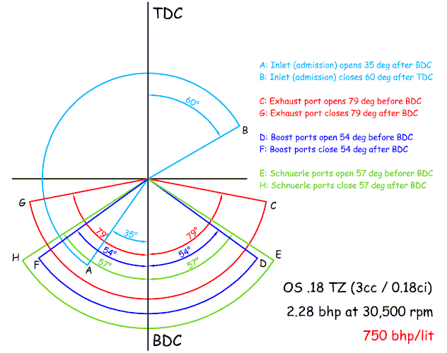
With disk valves (or preferably tube / drum valves), their rev limit increased several times:

Image

(an interesting article / technical analysis about the OS18TZ is at http://www.pattakon.com/tempman/osmz211 ... cnitro.pdf )


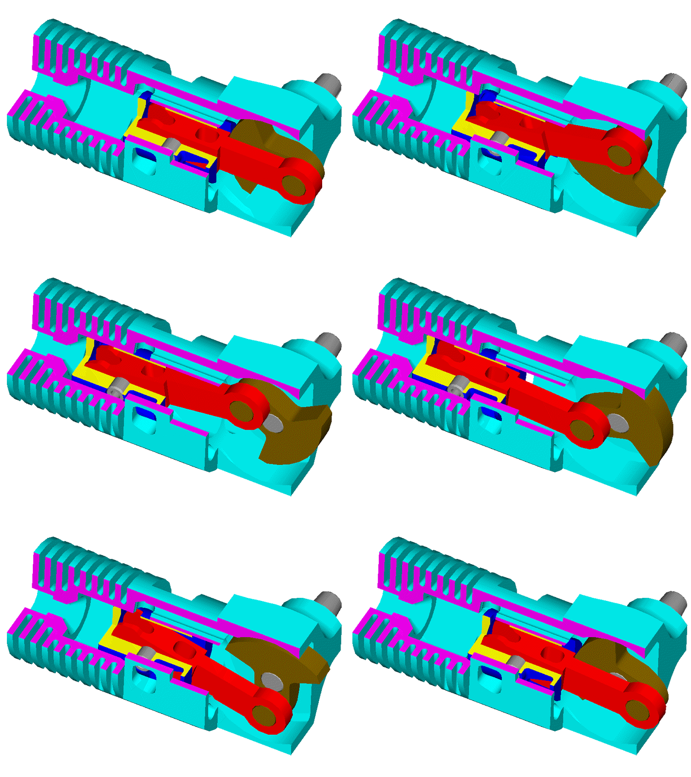
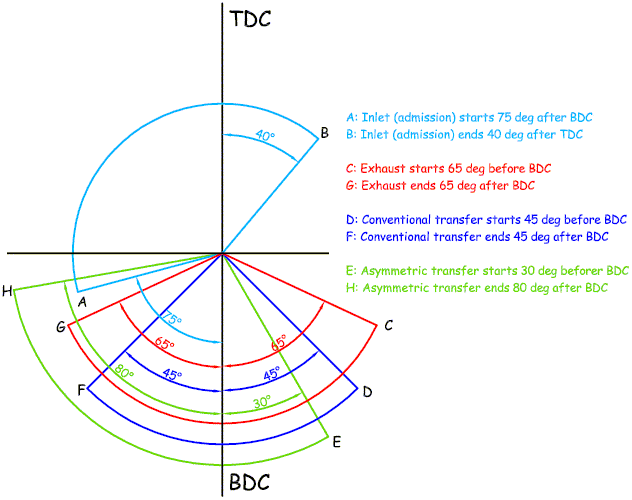
Here is a PatATi 2-stroke model engine design:

Image

Compare its asymmetric transfer with the symmetric transfer of the OS18TZ shown above.

Image


In the poppet-valve 4-stroke model / RC engines the rev limit remains at so low levels that big engines (say, like the Ducati Panigale 1299 with the 650cc capacity per cylinder) rev higher.


Here is a 4-stroke PatRoVa model engine design capable for really high revs:

Image


Thanks
Manolis Pattakos

J.A.W.
J.A.W.
109
Joined: 01 Sep 2014, 05:10
Location: Altair IV.

Re: 2 stroke thread (with occasional F1 relevance!)

Post

A few pages back T-C expressed some concerns per 2T flight, re: altitude/air-pressure/power loss..
..here is an academic engineering paper that considers some of those issues..

http://www.dtic.mil/dtic/tr/fulltext/u2/a558274.pdf

The travails encountered by the experimenter shows both the folly of not seeking realistic advice on 2T basics..
..& the wasteful approach often shown by the military, in 'trying to re-invent the wheel', or being gulled..
"Well, we knocked the bastard off!"

Ed Hilary on being 1st to top Mt Everest,
(& 1st to do a surface traverse across Antarctica,
in good Kiwi style - riding a Massey Ferguson farm
tractor - with a few extemporised mod's to hack the task).

Muniix
Muniix
14
Joined: 29 Nov 2016, 13:29
Location: Sydney, Australia

Re: 2 stroke thread (with occasional F1 relevance!)

Post

manolis wrote:
23 Apr 2017, 12:21
Hello Munnix:

You write:

“Using gas pressure via gas ports is never "at the same time" and why this method is never used as the primary means, it is used as a secondary means as it takes some time for the pressure to build up, like charging a capacitor, it also takes time to discharge.
Case in point - piston rings, their tension performs the seal and gas pressure used to assist only.
This gas porting increases crevice volume and loss of cylinder pressure, creates additional heat that needs to be removed.
. . .
The F1 bishop engine had ultra thin 3mm needle roller bearing of only 10mm width, these worked fine in endurance testing. Even surviving when the 'normal' f1 rods broke when running at MBT ignition timing low 30s btdc due to the fast combustion, fatigue eventually caused the rod to fail, they learned timing needed to be retarded slightly from mbt.”

The typical 4-stroke and 2-stroke PatRoVa design is not adding crevice volume, at all.
I was talking about using gas pressure
as the sole means for seal force?

you did not answer that!

The PatRoVa has massive leakage which is equivelent to crevice volume, your whole valve housing is crevice volume.
Doesn’t the 4-stroke Bishop rotary valve add crevice volume, too?

It does (the volume between the rotary valve, the cylinder head and the seals of the window at the top of the cylinder).
No it doesn't, gas is contained inside the cylinder by the sealing array right next to the window as close as possible.

Less than poppet valve engines as shown in the exhaust gas analyis with exceptionally low unburned hydrocarbons, the sealing array is very close to the window and combustion is concentrated in the window area,, where the vortices end up, the gas attaches and burns with the charge, very little fails to reach combustion temperature..

So next to no parasitic volumes, any blowby that does makes it past the 0.04mm2 total effective leakage area, is pulled in on the next intake. This is less than what leakes past the piston rings.
Put two “ultra thin 3mm needle roller bearing of only 10mm width” at some 130mm distance from each other, and support on them a thin-walled pipe (the Cross-Bishop rotary valve) having heavily asymmetrical structure with long / wide cuts (the ports) at its periphery, with an oblique separator at its middle and with highly asymmetric temperature distribution along and around the “pipe” (the one needle roller bearing works cold, the other has needles rolling on the red-hot “exhaust” side of the rotary valve, because the exhaust pipe is the inner ring of this needle roller bearing).

Then put a force of a couple of tons (20,000N) to press the middle part of the lower side of the pipe upwards, and you have the complete scene / picture.
Why lie about the bearings not being lubricated or cooled, you know the valve has oil flow for the bearings obviously needed. The valve has cooling run through the exhaust end, just like the liner does. You can see both the cooling channels in the valve in the photo of it with the CLK180 head, and the oil feed lines and the mounts for the coolant heat exchanger on top of the head.

I suggest you do some reading on radial loads on cylinders, there are some good publications on this. It is a science in it self with its own specific knowledge.

There are 1000 year old arch bridges in China that should not be standing according to our knowledge.
The sealing means of the Bishop can follow the resulting distortion / bending of the pipe-like valve and can keep the high pressure gas into the cylinder.
That is correct, the valve rotates with minimal clearence to its housing. Offers the highest cylinder filling and flow, 3D sintered valves now offer really cool geometry possibilities, the latest bosch motorsport injectors give even more power gains on port injection. Direct injection of LPG should work really well.
Don’t believe me, believe the guys of the Bishop Team:

QUOTE from the US7,621,249 patent,
Assignee: Bishop Innovation Limited,
Inventors: Wallis and Thomas:

“The purpose of the present invention is to provide a mechanism that minimises the flow of gas from one port to another, and in particular during those portions of the cycle where there is a large pressure difference between the ports and where the resulting flows will create problems with the operation of the engine.
That is mischevious refering to an obsolete patent, lodged in for patent protecion, it can be used in motorsport, that one is not the latest sealing patents Bishop filed. Remember I gave you the latest one, Cameron Donalds patent. The one that solves all the issues with clever overlapping. It identifies all the issues that a sealing array must provide and addresses them providing everthing the seals need to do. It shows all the paths, and flows, and the mechanisms used to address them.

Manolis,

Cross did not invent rotary valves, they are used in power steering, food processing, distribution of all sorts of things.

The Cross, Bishop and Watson valves are all different implementations of rotary valves for IC engines. As is your own, it just doesn't address all the issues but introduces some that need not exist. Issues I have raised and you refuse to even acknowledge.

Bishop optimised combustion from flame kernel to exhaust pipe, sealing took 16 years to perfect, with many incarnations, the F1 was the most suitable for purpose, the low emissions sealing array is for production engines, were a second row of circumferential seals can be used, for near zero emissions. This is the current method,next to nothing gets past them. These secondary seals need only minimal sealing force so very little parasitic losses.
It is now time to take another look at the PatRoVa and to think how many issues / problems it avoids with its simple / different architecture.
As detailed you have too many inherent flaws in the design as previously raised, sealing, insufficient flow, loss of pressure wave action, increased pumping losses, thermal issues ....

Trying to solve the non issue of combustion pressure, you split the flows and turned them into one another.
Loosing valuable flow capacity and reducing the flow coefficient many times on an already low flow. Introducing fluid flow issuesj that only 3D CFD while allow you to understand, and it will be complex to implement the motions of the valve into the simulation.

In Finishing this discusion I note that while the Bishop valve lowers the head hight making a low profile head, it does overhang the cylinder housing a little in the valve axis, not a lot but not as tight as the sides. The cooling is exceptionally efficient for the head, just simple drilled and pluged galleries along the seals and next to the ignition devices, be it spark plugs or jet ignition units.

Marc
Last edited by Muniix on 24 Apr 2017, 18:00, edited 3 times in total.

Pinger
Pinger
9
Joined: 13 Apr 2017, 17:28

Re: 2 stroke thread (with occasional F1 relevance!)

Post

J.A.W. wrote:
24 Apr 2017, 11:46
A few pages back T-C expressed some concerns per 2T flight, re: altitude/air-pressure/power loss..
..here is an academic engineering paper that considers some of those issues..

http://www.dtic.mil/dtic/tr/fulltext/u2/a558274.pdf

The travails encountered by the experimenter shows both the folly of not seeking realistic advice on 2T basics..
..& the wasteful approach often shown by the military, in 'trying to re-invent the wheel', or being gulled..
I skim read the paper...but what I don't understand is how he used a Lambda sensor in calibrating the EFI. Surely charge loss caused by short circuiting would result in oxygen being present in the exhaust and the Lambda sensor unable to distinguish if it was from excess air that had been through the combustion process or merely air that bypassed combustion.
My understanding is that until charge loss can be eliminated, O2 sensors are of no use in any form of AFR monitoring (or control) Am I wrong?

Muniix
Muniix
14
Joined: 29 Nov 2016, 13:29
Location: Sydney, Australia

Re: 2 stroke thread (with occasional F1 relevance!)

Post

A useful way of compensating for air density at altitude has been the use of the Pressure wave supercharger.

It uses gas dynamics to exchange exhaust pressure into the intake, rather than the less efficient mechanical compression.

Polaris Swiss Auto held the patents on these and had several projects going with VW and AMG etc. But it seams now that Polaris bought them they have sold the patents, so bye bye Mission and Victory motorcycles and now the PWS is no more. I'm trying to get a unit for development but doesn't look good.

Pinger
Pinger
9
Joined: 13 Apr 2017, 17:28

Re: 2 stroke thread (with occasional F1 relevance!)

Post

I thought the PWS (initially called Comprex) was abandoned due to it overheating the incoming air. (Not by compression, but by proximity to the outgoing exhaust gas).

Muniix
Muniix
14
Joined: 29 Nov 2016, 13:29
Location: Sydney, Australia

Re: 2 stroke thread (with occasional F1 relevance!)

Post

Pinger wrote:
24 Apr 2017, 14:51
J.A.W. wrote:
24 Apr 2017, 11:46
A few pages back T-C expressed some concerns per 2T flight, re: altitude/air-pressure/power loss..
..here is an academic engineering paper that considers some of those issues..

http://www.dtic.mil/dtic/tr/fulltext/u2/a558274.pdf

The travails encountered by the experimenter shows both the folly of not seeking realistic advice on 2T basics..
..& the wasteful approach often shown by the military, in 'trying to re-invent the wheel', or being gulled..
I skim read the paper...but what I don't understand is how he used a Lambda sensor in calibrating the EFI. Surely charge loss caused by short circuiting would result in oxygen being present in the exhaust and the Lambda sensor unable to distinguish if it was from excess air that had been through the combustion process or merely air that bypassed combustion.
My understanding is that until charge loss can be eliminated, O2 sensors are of no use in any form of AFR monitoring (or control) Am I wrong?
They did similiar research on the same engine with putting a pressure wave supercharger on it.

Bottom line they got their number wrong and it didn't work as intended.

Marc

Muniix
Muniix
14
Joined: 29 Nov 2016, 13:29
Location: Sydney, Australia

Re: 2 stroke thread (with occasional F1 relevance!)

Post

Muniix wrote:
24 Apr 2017, 14:32
manolis wrote:
23 Apr 2017, 12:21
Hello Munnix:

You write:

“Using gas pressure via gas ports is never "at the same time" and why this method is never used as the primary means, it is used as a secondary means as it takes some time for the pressure to build up, like charging a capacitor, it also takes time to discharge.
Case in point - piston rings, their tension performs the seal and gas pressure used to assist only.
This gas porting increases crevice volume and loss of cylinder pressure, creates additional heat that needs to be removed.
. . .
The F1 bishop engine had ultra thin 3mm needle roller bearing of only 10mm width, these worked fine in endurance testing. Even surviving when the 'normal' f1 rods broke when running at MBT ignition timing low 30s btdc due to the fast combustion, fatigue eventually caused the rod to fail, they learned timing needed to be retarded slightly from mbt.”

The typical 4-stroke and 2-stroke PatRoVa design is not adding crevice volume, at all.
I was talking about using gas pressure
as the sole means for seal force?

Once again, you didn't answer the question and instead did the straw man of;

Dont look there, look over here.

The PatRoVa has massive leakage which is equivelent to crevice volume, your whole valve housing is crevice volume. You have no effective sealing method against the high cylinder pressure.

Now please answer these two questions.
Doesn’t the 4-stroke Bishop rotary valve add crevice volume, too?

It does (the volume between the rotary valve, the cylinder head and the seals of the window at the top of the cylinder).
No it doesn't, gas is contained inside the cylinder by the sealing array right next to the window as close as possible.
Less than poppet valve engines as shown in the exhaust gas analyis with exceptionally low unburned hydrocarbons, the sealing array is very close to the window and combustion is concentrated in the window area,, where the vortices end up, the gas attaches and burns.

So next to no parasitic volumes, any blowby that does makes it past the 0.04mm2 total effective leakage area, is pulled in on the next intake. this is less than what leakes past the piston rings.
Put two “ultra thin 3mm needle roller bearing of only 10mm width” at some 130mm distance from each other, and support on them a thin-walled pipe (the Cross-Bishop rotary valve) having heavily asymmetrical structure with long / wide cuts (the ports) at its periphery, with an oblique separator at its middle and with highly asymmetric temperature distribution along and around the “pipe” (the one needle roller bearing works cold, the other has needles rolling on the red-hot “exhaust” side of the rotary valve, because the exhaust pipe is the inner ring of this needle roller bearing).

Then put a force of a couple of tons (20,000N) to press the middle part of the lower side of the pipe upwards, and you have the complete scene / picture.
I suggest you do some reading on radial loads on cylinders, there are some good publications on this. It is a science in it self with its own specific knowledge.

The roller bearings have lubrication running through them and you know that, stop lying, it is not in keeping with this forum, stop misleading people. Others will report you. I dont have to.
The sealing means of the Bishop can follow the resulting distortion / bending of the pipe-like valve and can keep the high pressure gas into the cylinder.
That is correct, the valve rotates with minimal clearence to its housing. Offers the highest cylinder filling and flow, 3D sintered valves now offer really cool geometry, the latest bosch motorsport injectors give even more power gains on port injection. Direct injection of LPG should work really well.
Don’t believe me, believe the guys of the Bishop Team:

QUOTE from the US7,621,249 patent,
Assignee: Bishop Innovation Limited,
Inventors: Wallis and Thomas:

“The purpose of the present invention is to provide a mechanism that minimises the flow of gas from one port to another, and in particular during those portions of the cycle where there is a large pressure difference between the ports and where the resulting flows will create problems with the operation of the engine.
That is mischevious refering to an obsolete patent, put in for patent protecion only, it can be used in motorsport, that one is not the latest sealing patents Bishop filed.

Manolis,
Cross did not invent rotary valves, they are used in power steering, food processing, distribution of all sorts of things.

The Cross, Bishop and Watson are all different implementations of rotary valves for IC engines.

Bishop optimised combustion from flame kernel to exhaust pipe, sealing took 16 years to perfect, with many incarnations, the F1 was the most suitable for it, the low emissions sealing array are for production engines, were a second row of circumferential seals can be used, for near zero emissions. This is the current method,next to nothing gets past them. These secondary seals need only minimal sealing force so very little parasitic losses.
It is now time to take another look at the PatRoVa and to think how many issues / problems it avoids with its simple / different architecture.
As detailed you have too many inherent flaws in the design as previously raised, sealing, insufficient flow, loss of pressure wave action, increased pumping losses....

Trying to solve the non issue of combustion pressure, you split the flows and turned them into one another.
Loosing valuable flow capacity and reducing the flow coefficient many times on an already low flow.

In Finishing this discusion I note that while the Bishop valve lowers the head hight making a low profile head, it does overhang the cylinder housing a little in the valve axis, not a lot but not as tight as the sides.

And remember to quote your intake velocity data and trapped air mass from your 1d simulation to match the original engines performance.

Everyone does these calculations as part of initial design requirements.

Marc
[/quote]
Last edited by Muniix on 25 Apr 2017, 18:17, edited 2 times in total.