2 stroke thread (with occasional F1 relevance!)

All that has to do with the power train, gearbox, clutch, fuels and lubricants, etc. Generally the mechanical side of Formula One.
manolis
manolis
107
Joined: 18 Mar 2014, 10:00

Re: 2 stroke thread (with occasional F1 relevance!)

Post

Hello Tommy Cookers.

You write:
“but 1 kg of induced air in the engine running on 'straight' ie 100% methanol fuel requires 156 gm of methanol
if we take 80% of that and add nitro to make a 20/80 nitro/methanol blend we add far less nitro than 20% (111 gm) of our 100% nitro
we actually about 6% (of the nitro in our 100% nitro) to make '20%' nitro/methanol fuel - crudely this appears to increase power by 8% “


It is different than this.

Let’s start with 1Kg induced air that requires 156gr “straight” ethanol for a complete combustion (stoichiometric).

We substitute the 20% of the 156gr of the ethanol (i.e. the 31.2gr of the ethanol) by equal weight of nitromethane, which requires for its complete combustion 31.2/588= 0.053Kg of air.

So we have 156-31.2=124.8gr of methanol and 31.2gr of nitro, and 1Kg of air in the cylinder.

The reduced quantity of the methanol leaves 0.2Kg of air for the combustion of the 31.2gr nitro. But this quantity of nitro requires only 0.053Kg of air.
This means that only 0.853Kg of the air would be used (lean burn).

1/0.853=1.17

Multiplying the 124.8gr of the methanol by 1.17, multiplying also the 31.2gr of the nitro by the same factor 1.17, we take: 146gr ethanol and 36.5gr nitromethane.

So, for 1Kg of air, instead of 156gr straight ethanol, we can use 146gr ethanol and 36.5gr of nitro, i.e. in total 182.5gr of fuel (17% more - in weight - than the initial straight ethanol).

I.e. we substitute 36.5gr nitro for 10gr ethanol to have a stoichiometric air-fuel mixture.

This increases the overall thermal content of the fuel that can be burnt by 1Kg air.


**************************************************************************************************

You also write:

“btw 100% nitrobenzene would give less power than 100% methanol, but is valued at 0.5% as a combustion improver for the 99.5% constituents
so there must be combustion improvement due to the nitromethane in '20%' nitro fuel
OS originally stated the power as 1.83 hp - but 2.28 hp on 20% nitro”


Having the energy content of the two fuels (nitro and methanol), here is a calculation of the increase of the power with nitro:

156gr of ethanol have 0.156*19.7MJ/Kg=3.07MJ energy

146gr of ethanol + 36.5gr of nitromethane have 0.146*19.7MJ/Kg + 0.0365*11.3MJ/Kg = 2.88MJ + 0.41MJ = 3.29MJ

This gives an increase of 3.29/3.07 = 1,07 or 7%

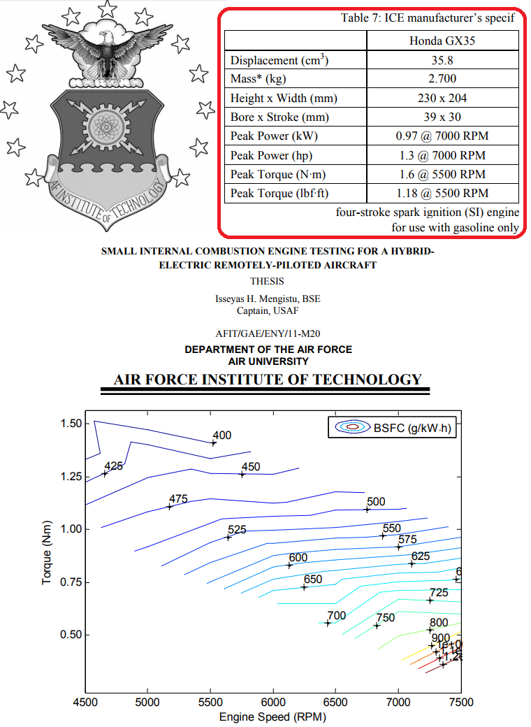
If the 2.28bhp is correct for the 20% nitro-fuel, with straight ethanol the OS18TZ should provide : 2.13bhp.

**************************************************************************************************

(in the previous it was not taken under account the difference in the cooling effect of the different fuels).

Thanks
Manolis Pattakos
Last edited by manolis on 05 Nov 2017, 07:41, edited 2 times in total.

manolis
manolis
107
Joined: 18 Mar 2014, 10:00

Re: 2 stroke thread (with occasional F1 relevance!)

Post

Hello Tommy Cookers.

Regarding the PJ-8 fuel (your link http://digitalcommons.mtu.edu/cgi/viewc ... ntext=etds ),

the PatRoVa rotary valve four-stroke:

Image

is rid of red-hot exhaust valves (and of other hot spots) inside the combustion chamber.

This makes it ideal for high, or extreme, compression ratios without detonation / knocking.

This characteristic fits with the PJ-8 fuel, too.

The uniform temperature walls of the combustion chamber of the PatRoVa can be kept substantially hotter than in the conventional poppet valve 4-strokes (say, at half the temperature of the conventional exhaust poppet valves).

The military like the PJ-8 because of the absence of volatile fractions.

But it is the volatile fractions that ignite first and help the rest fractions to evaporate and get finally burnt.

With the PatRoVa, the reduced wall area and the beefy/concentrated (during the combustion) combustion chamber, together with the higher (but uniform) wall temperature are what the PJ-8 fuel needs.

Thanks
Manolis Pattakos

manolis
manolis
107
Joined: 18 Mar 2014, 10:00

Re: 2 stroke thread (with occasional F1 relevance!)

Post

Hello all.

The OS18TZ two stroke model engine shown in the previous post is, undoubtedly, a powerful, for its size, 2-stroke.

An interesting characteristic of its design is the rotary drum inlet valve that provides air-fuel mixture to the crankcase through a 7.5mm diameter hole in the crankshaft.

Here is its port timing:

Image

The inlet (or intake, or admission) duration is only 205 crank degrees.

I.e. a hole of 7.5mm diameter that opens for only 205 degrees per crank rotation, provides the air-fuel mixture to a cylinder having 16mm bore.

With 15mm stroke it is a near square cylinder, as happens with most high performance 2-strokes.

Inlet port area to piston area: 7.5^2/16^2 = 22%


For comparison, let’s take a miniature 4-stroke having the architecture of the Ducati Panigale 1199 (60.8mm stroke, 112mm bore).

For the same capacity (3.02cc) the dimensions of the 4-stroke should be:
bore 19.2mm,
stroke 10.4mm.
bore to stroke ratio 19.2/10.4 = 1.84 = 112/60.8, i.e. as in the real Ducati Panigale 1199cc which has an extremely over-square design.

For the same mean piston speed with the OS18TZ, the 30,500rpm (wherein the 2-stroke provides its peak power) become (15/
10.4)*30,500=44,000rpm for the over-square miniature 4-stroke.

With each inlet valve of the real Ducati Panigale 1199 being 46.8mm, the miniature Ducati comprises two poppet valves, each having 8mm diameter (similarity).
The valve seat occupies some area, so each intake poppet valve of the miniature Ducati Panigale can be considered as equivalent with a hole having 7.5mm diameter (i.e. each poppet valve has about the same flow capacity with the unique inlet port of the OS18TZ).

The duration of the intake valves of the 4-stroke is ~270 degrees, i.e. it is 30% longer than the duration of the inlet port of the OS18TZ.
Besides, the opening and closing ramps of the 4-stroke poppet valves are steep in comparison to the inlet port of the 2-stroke wherein the opening and closing is progressive / smooth.

At 44,000rpm (wherein the mean piston speed is ~15m/sec) the 4-stroke has a valve-time area more than 80% larger than the port-time-area of the 2-stroke OS18TZ running at only 30,500rpm.

With the same specific torque with the Panigalle 1199 (110mN/lt), the power of the 4-stroke at 44,000rpm is calculated at: 2bhp.

With its valve-time-area as calculated above, the 4-stroke can breathe efficiently until 60,000rpm.


Even if the miniature Desmo cylinder head could stand the punishment of the 44,000rpm (or of the 60,000rpm), the required machining seems impossible.


With the PatRoVa rotary valve on the cylinder head:

Image

the machining is simple, and the 60,000rpm OK.


Following a different path / approach:
Applying the “similarity”, and based on the 195bhp @ 10,750rpm of the real Panigale, the miniature Panigale should make 2,85bhp at 62,700 rpm (10,750*112/19.2 = 62,700)

Thanks
Manolis Pattakos

AJI
AJI
27
Joined: 22 Dec 2015, 09:08

Re: 2 stroke thread (with occasional F1 relevance!)

Post

I love the detail in this thread, so I thought I'd give you guys some inspiration.

My genius neighbour made this little old 2 stroke. V16, 2.56litre, supercharged.

Image

manolis
manolis
107
Joined: 18 Mar 2014, 10:00

Re: 2 stroke thread (with occasional F1 relevance!)

Post

Hello AJI

Congratulations to your neighbour for his 16-cylinder 2-stroke.

There is a lot of metal work in it.
And it seems he is not using expansion chambers. . .


Ask him to take a look at the PatATE, at http://www.pattakon.com/pattakonPatATE.htm

It seems it takes only 1/15 of the pain and a small fraction of the cost to make a PatATE single cylinder prototype.

If he is interested, tell him to drop me an e-mail ( man@pattakon.com ) with the cost.

Thanks
Manolis Pattakos

AJI
AJI
27
Joined: 22 Dec 2015, 09:08

Re: 2 stroke thread (with occasional F1 relevance!)

Post

manolis wrote:
06 Nov 2017, 14:36
Congratulations to your neighbour for his 16-cylinder 2-stroke.

There is a lot of metal work in it.
And it seems he is not using expansion chambers. . .
Thanks Manolis,

I’ll tell him, but he’s kind of eccentric and very introverted, so, I will probably get into trouble for posting links to his website (which is maintained by others and he is constantly threatening to take down...)

The 2 stroke was just a ‘lark’ for him, if you can believe it! His real passion is rotary valve anything.
He has designed and built dozens of rotary valve engines now. They all work, they are all hand drawn and they are all hand made with only a mill and a lathe! That’s right, he doesn’t use CAD and nothing is made with a CNC!

This is his most recent rotary valve engine.
Image

uniflow
uniflow
36
Joined: 26 Jul 2014, 10:41

Re: 2 stroke thread (with occasional F1 relevance!)

Post

Ha ha, AJI you mean he actually builds stuff, good on him, I like his style! :D :D

AJI
AJI
27
Joined: 22 Dec 2015, 09:08

Re: 2 stroke thread (with occasional F1 relevance!)

Post

uniflow wrote:
07 Nov 2017, 01:05
Ha ha, AJI you mean he actually builds stuff, good on him, I like his style! :D :D
He's truly an inspiration for any engine builder, and when you talk to him (which is almost impossible) he's so modest and humble that you can't help but feel inferior (in a good way, if that makes sense?).

manolis
manolis
107
Joined: 18 Mar 2014, 10:00

Re: 2 stroke thread (with occasional F1 relevance!)

Post

Hello AJI

You write:
"The 2 stroke was just a ‘lark’ for him, if you can believe it! His real passion is rotary valve anything.
He has designed and built dozens of rotary valve engines now. They all work, they are all hand drawn and they are all hand made with only a mill and a lathe! That’s right, he doesn’t use CAD and nothing is made with a CNC!"


So,

instead of the 2-stroke, show him the PatRoVa Rotary Valve (at http://www.pattakon.com/pattakonPatRoVa.htm ) :


No need to look carefully to see at what "manufacturing accuracy" the PatRoVa prototype was made:

Image

Image

Image


By the way: only a small lathe (at "scrap" condition) was used, and no mill at all.

The underneath engine was available from an old project (harmonic engine; more at http://www.pattakon.com/pattakonPPE.htm#harmonic )


By a look at your neighbour's rotary valve V-2 prototype engine, it is obvious that with the PatRoVa rotary valve:

he needs one only "moderate / uniform temperature" rotary valve per cylinder (instead of a cold intake rotary valve and a red-hot exhaust rotary valve),

the "port area" doubles (because the same ports are used for the intake and the exhaust, meaning uniform combustion chamber temperature, allowing even higher compression ratio),

the eight heavy bearings required for the support of the rotary valves on the two cylinder heads are replaced by four "tiny" roller bearings,

the srong forces on his rotary valves during the combustion are 100% eliminated in the PatRoVa rotary valve:

Image

Image

thanks to the absence of loads between the sealing surfaces there is no need for lubrication in the cylinder head,

etc, etc.


When he sees how big is the difference of the PatRoVa rotary valve from the prior art . . .

Thanks
Manolis Pattakos

Pinger
Pinger
9
Joined: 13 Apr 2017, 17:28

Re: 2 stroke thread (with occasional F1 relevance!)

Post

Dividing the ratio of volumes into the ratio of surface areas (at TDC - where the bulk of heat loss occurs) gives a ratio of surface:volume of 0.006 ie, the W's surface area to volume ratio is 0.006 of that of the OS. Multiplying by 436 to correct for speed gives a figure of 2.68. That is, the W's heat loss is 2.68 time greater than the OS's.
That figure will be lower in practice due to lean combustion in the W but unless I have seriously erred here the OS by dint of its very high speed suffers less from heat loss than does the W.

Does anyone want to comment on this? If my figures are correct it does question the absolute wisdom of slow running as the route (ignoring friction for now) to maximising fuel efficiency even when the surface to volume ratio is highly advantageous as it is with the W.

Pinger
Pinger
9
Joined: 13 Apr 2017, 17:28

Re: 2 stroke thread (with occasional F1 relevance!)

Post

manolis wrote:
03 Nov 2017, 07:24

Question:
When a molecule of fuel is burnt at the center of the combustion chamber heating only the surrounding air (i.e. the working medium),
and when a molecule of the fuel is burnt in touch with the walls (heating mainly the metal and not the working medium),
what is the difference in thermal efficiency?

Manolis Pattakos
Burning fuel with a cushion of insulating air around it apart from being difficult to achieve, will inevitably result in a larger swept volume for the same torque output - no matter what other advantage(s) can be gleaned.

Fuel in too close proximity to the chamber wall will likely not burn (or burn so late in the cycle to be of little value) as it will lose the heat required to ignite it faster than the flame front can provide it. So called 'quench zones' and their attendant contribution to UBHC - a curse of the liquid fuelled engine.

manolis
manolis
107
Joined: 18 Mar 2014, 10:00

Re: 2 stroke thread (with occasional F1 relevance!)

Post

Hello Pinger

You write:
“Dividing the ratio of volumes into the ratio of surface areas (at TDC - where the bulk of heat loss occurs) gives a ratio of surface:volume of 0.006 ie, the W's surface area to volume ratio is 0.006 of that of the OS. Multiplying by 436 to correct for speed gives a figure of 2.68. That is, the W's heat loss is 2.68 time greater than the OS's. “


In the high revving OS18TZ miniature engine the bulk of the fuel is burnt substantially after the TDC (the combustion continues even after the opening of the exhaust port), while the fuel in the giant marine is burnt near the TDC.

This gives a significant efficiency advantage to the big engine because the fuel is burnt at high expansion ratio.
In comparison, think of a fuel droplet burnt at 80 degrees after the TDCin the OS18TZ: the “geometrical” expansion ratio is 2:1 (the actual expansion ratio is even lower), and the thermal efficiency is way lower than it was for the droplets of fuel that were burnt at exactly the TDC (expansion ratio 11:1).

I.e. we have one more significant factor for increased heat loss; and as with the distance of the flame from the cylinder walls, this factor is not proportionally related with the time.


You also write:

“Burning fuel with a cushion of insulating air around it apart from being difficult to achieve, will inevitably result in a larger swept volume for the same torque output - no matter what other advantage(s) can be gleaned.
Fuel in too close proximity to the chamber wall will likely not burn (or burn so late in the cycle to be of little value) as it will lose the heat required to ignite it faster than the flame front can provide it. So called 'quench zones' and their attendant contribution to UBHC - a curse of the liquid fuelled engine.”


The “slow steaming” (“operation of the ship at a lower speed than normal”, more at https://www.wartsila.com/docs/default-s ... f?sfvrsn=0 ) is another way to see the affect of the time on the overall thermal efficiency and on the thermal loss.

A giant 2-stroke is driving directly the propeller: the rpm of the propeller and the rpm of the engine are the same.

At “slow steaming” the engine runs at lower and at substantially lower revs.

Image

According the above graph of Wartsila, the green line “says” that at 26knots the BSFC is 168gr/kWh, which is 48% BTE (Brake Thermal Efficiency; note: on Heave Fuel Oil), while at 13knots (extend the green line to the left) the BSFC increase at 181gr/kWh (45% BTE).

I.e. while the time doubles (if the engine at 26knots operates at 70rpm, at 13knots it operates at 35rpm), the BTE drops by only 3%.

Estimate the increase of the thermal loss and compare it with the 100% increase of time provided for thermal loss.


Worth to mention:
The engine is optimized at 26knots / 70rpm, not at 13knots / 35rpm.
Without the "optimization" (the "hole" in the BSFC curve) around 26mph, the difference in BTE from 70rpm to 35rpm (where the time for thermal loss doubles) would be around 1.5%.

Thanks
Manolis Pattakos

Pinger
Pinger
9
Joined: 13 Apr 2017, 17:28

Re: 2 stroke thread (with occasional F1 relevance!)

Post

manolis wrote:
09 Nov 2017, 10:07
In the high revving OS18TZ miniature engine the bulk of the fuel is burnt substantially after the TDC (the combustion continues even after the opening of the exhaust port), while the fuel in the giant marine is burnt near the TDC.

Fair point. In CI combustion, the effect there is referred to as the 'cut off ratio'. The principle is the same.

manolis wrote:
09 Nov 2017, 10:07
I.e. while the time doubles (if the engine at 26knots operates at 70rpm, at 13knots it operates at 35rpm), the BTE drops by only 3%.
The mere 3% drop in BTE though must in part be due to running at lower torque level. At the point that more fuel is supplied to accelerate to a higher cruise speed, the reduction in BTE would surely be greater (at that still low crankshaft speed).

manolis
manolis
107
Joined: 18 Mar 2014, 10:00

Re: 2 stroke thread (with occasional F1 relevance!)

Post

Hello Pinger.

Here is the BSFC for the Honda GX35, a small (36cc) 4-stroke engine:

Image

Minimum BSFC: 400gr/kWh at 5,000rpm (5m/sec mean piston speed), near full load.

This BSFC means a 20% peak BTE (Brake Thermal Efficiency).
The rest 80% of the fuel energy is consumed (directly or inderectly) to thermal loss.

Compare with the slow revving giant marine 2-strokes with the 50% BTE and the longer time for thermal loss..

Thanks
Manolis Pattakos

wizz33
wizz33
0
Joined: 25 Aug 2017, 07:47

Re: 2 stroke thread (with occasional F1 relevance!)

Post