2 stroke thread (with occasional F1 relevance!)

All that has to do with the power train, gearbox, clutch, fuels and lubricants, etc. Generally the mechanical side of Formula One.
gruntguru
563
Joined: 21 Feb 2009, 07:43

Re: 2 stroke thread (with occasional F1 relevance!)

Post

Good points.
je suis charlie

Pinger
9
Joined: 13 Apr 2017, 17:28

Re: 2 stroke thread (with occasional F1 relevance!)

Post

PhillipM wrote:
04 Feb 2019, 00:11
Heavy load is exactly where they take the highest angles - when the car is at low speeds in a low gear with the most wheel torque being delivered.
I thought the shafts were arranged to be (under conditions of weight transfer) horizontal ie as close to zero angles under full throttle first gear acceleration. Not to protect the joints (on FWD) but to minimise torque steer.
Full torque and steering angle - nah.

PhillipM
385
Joined: 16 May 2011, 15:18
Location: Over the road from Boothy...

Re: 2 stroke thread (with occasional F1 relevance!)

Post

Not generally possible on longer travel suspension/jacked up SUV's, especially when the joints doing the most angle are at the front in droop. You don't care about the rear joints that are straight during compression because their driveline angles are tiny compared anyway.

And yes, the most torque transmission will generally be seen at low speeds where the most steering angle is used, simply from virtue of being in the lowest gear, driveline shunt and usually manuveuring, parking, etc. Even in terms of race use the place you'd want something like this would be the front of WRC cars or similar where you would still be producing the most torque at low speeds where you have the highest steering angles.

User avatar
PlatinumZealot
550
Joined: 12 Jun 2008, 03:45

Re: 2 stroke thread (with occasional F1 relevance!)

Post

noice wrote:
02 Feb 2019, 13:49
Sorry to quote from way back but there is awful info on 2 stroke slow speed engines.
roon wrote:
16 Jul 2018, 03:56
gruntguru wrote:
16 Jul 2018, 01:56


You mean "reduced blow by"?
Blow-by designed in, may be what he means. The piston doesn't need rings nor touch the cylinder wall. The volume beneath the cylinder can be used as a pump as a sort of forced induction. Blow-by would manifest as a sort of EGR, while being oil-free. The piston rod is what gets sealed from the crankcase, and also acts as the piston guide.
This is all incorrect. There used to be PUP (Piston Underside Pumping) in some engines to use the underside of the piston to provide some pressure but I've never seen in use, only description in text.

Blow by will ruin the cylinder, there is 3 compression rings and one oil control ring.

The piston touches the wall, look at the bands on the piston skirt below the rings, they are made of bronze and allow the rings not to get overloaded by friction.

https://i.imgur.com/mmkaJ2Y.jpg

Piston rod is sealed by the stuffing box, it is a series of brass and cast iron scraper rings that are spring loaded against the piston rod. They cannot support any weight. The crosshead and bands on the piston skirt locate the piston.

https://i.imgur.com/lmcXytJ.jpg
PlatinumZealot wrote:
19 Jul 2018, 01:03
The speed is just above 103 rpm to 125 rpm at full load for the slow speed engines ( power generation - I am not familiar with their use on ships, but ships require variable operating loads and speeds). You can hear each explosion when you stand beside the cylinders.
Smaller two stroke engines run at 90-130 rpm, stuff in the 10,000-20,000HP range. Larger engines will be 90-100rpm area, long stroke engines may be lower than that.

The bigger the ship, normally the propeller becomes larger, tip speed starts to cause cavitation that damages the blade so the speed of the shaft is lowered.

130 rpm is the highest I have seen on 600ft tankers with a 16-18KHP engine.

94 rpm is the lowest I have seen on 1000ft containership with a 77KHP engine.

There is of course ships above and below this, but of the 20 or so ships I have been an engineer on, that is the trend I have seen.
If the engine is used for power generation the speed is determined by the grid frequency once you are on load and it must hold that rpm at close to full load. Much much more demanding than marine applications.
🖐️✌️☝️👀👌
🟤🟤 Coco puffs are my favourite too! 🟤🟤

User avatar
PlatinumZealot
550
Joined: 12 Jun 2008, 03:45

Re: 2 stroke thread (with occasional F1 relevance!)

Post

Tommy Cookers wrote:
03 Feb 2019, 13:16
recently a stroked version of a slow-speed marine engine was announced as able to run continuously at 7 rpm for 10% power
in 1911 the first Diesel loco had direct drive (2 stroke V4 engine run at high load as a compressed air engine up to 7 mph)
it worked tolerably well - well enough to break its transmission
others were similar in design philosophy (eg even using steam for starting at full load)

hybrid F1 is fuelled notionally for constant torque up to 10500 rpm
and has technology to control fuelling/combustion to '0 rpm' rate - as true Diesels were doing over a century ago
with eg its electrically driven supercharging F1 could have its maximum torque notionally at 0 rpm
as did such differentially boosted CI engines as were made and successfully tested 50 years ago

surely it's now possible to make a piston ICE that will directly drive an F1 car (or a road car) ?
the technology exists (controlling combustion rate and charge) for the ICE to pull maximally (ie hill starts) from 0 rpm
(ok it might always be better to involve the electric motor with the ICE in road vehicles)
At my job the giant slow speed diesel does 103 rpm at close to full speed.. but when its starting up it does so at about 20 rpm. It was not designed to be efficient at that speed though for various reasons.
The rpm seems to be a function of the size of the engine (the stroke), the combustion propogation, the mass of the moving parts, the fluid dynamics of the lubrication and other things. Generally I think you would want the lowest rpm you can get away with because it is less wear on the parts - while still being the right Rpm for a generator (the number of poles it has) and meeting the propulsion speed/ electric frequency you want. It seems everything seems to be designed around getting the lowest rpm you can get away with.
🖐️✌️☝️👀👌
🟤🟤 Coco puffs are my favourite too! 🟤🟤

manolis
107
Joined: 18 Mar 2014, 10:00

Re: 2 stroke thread (with occasional F1 relevance!)

Post

Hello PhillipM

Quote from http://www.pattakon.com/pattakonPatBalDan.htm :

To the question:

"Why the larger operating angles are preferable / significant / important?"

it replies the following quote from the officially published (2007) TECHNICAL REVIEW No.75 of NTN (one of the largest, worldwide, maker and supplier of car CVJ's and car transmission parts):

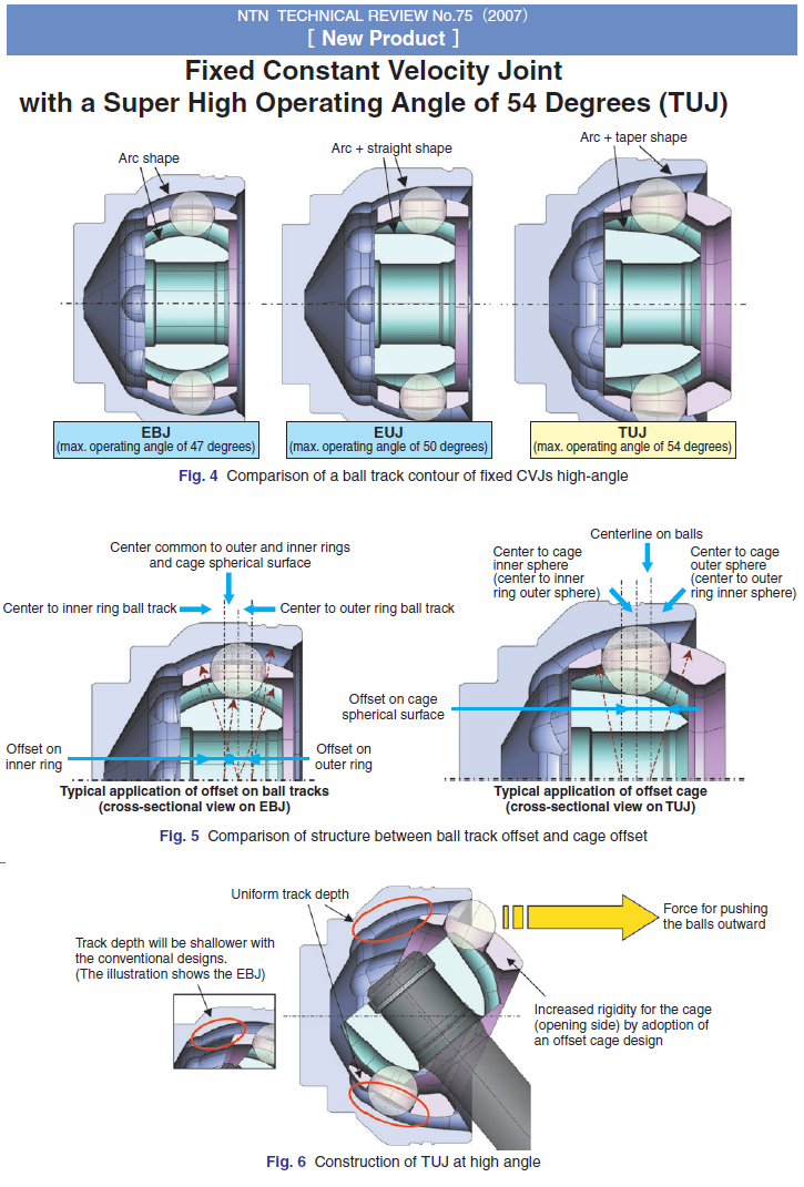
"Fixed Constant Velocity Joint with Super High Operating Angle of 54 Degrees
. . .
This maximum operating angle (54 degrees) for automotive driveshaft is currently the highest in the automotive industry.
The increase of 4 degrees in operating angle means that the minimum turning radius of an average medium-sized FF car can be decreased by approximately 70cm (13%) or the wheelbase of such class of a car can be enlarged by approximately 40cm (15%) while maintaining a minimum turning radius.
In other words, a medium-sized can feature a turning radius of a compact car or the passenger space of a larger car allowing designers more flexibility in consideration of layout and design"

End of Quote

Where the limitation of the maximum operating angle of the ball CVJ's comes from?

As the angle of the universal joint increases, the shaft secured to the inner race member hits on (or collides with) the tracks formed on the outer race member. From another viewpoint: at the greater operating angles, the tracks of the outer race member "cut" the second shaft limiting its diameter.

For instance:
With "arc-shaped" tracks, for a bending angle of 54 degrees each track on the outer race member needs to extend angularly for at least 54/2=27 degrees at each side of the bisecting plane of the angle formed by the rotation axes of the two shafts. At the maximum operating angle between the shafts (54 degrees), the one end of the track on the outer race covers 27+54=81 degrees, leaving the rest 9 degrees for the second shaft to pass, which means a total of 2*9=18 degrees "free" space for the second shaft to pass, which degreases substantially the diameter (and the strength) of the joint. With a, say, 70mm diameter of the arcshaped grooves, 18 degrees correspond to maximum possible second shaft diameter of 11mm (70mm*sin(18/2)=10.95mm).

This explains the need for unconventionally shaped tracks (arc+linear or arc+taper) in order to achieve larger operating angles (50 degrees in the first case, and the world top 54 degrees in the second case).

According the previous quote and calculations, the state-of-the-art automotive CVJ is impossible (geometrically) to operate with an angle of 60 degrees between its shafts.

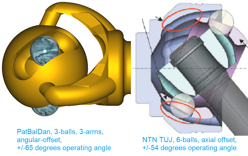
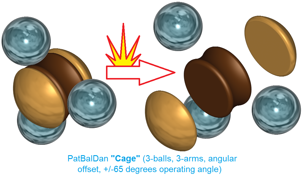
The PatBalDan CVJ (or universal joints)

Image

is capable, among others, for substantially higher bending angles, even for over 80 degrees (which is 50% larger than the current world maximum). And this can be done with any kind of tracks and/or offset (curved, curved+linear, curved+taper, axial offset, angular offset, cage offset etc).

According the "rule of thump" mentioned in the previous quote, with each 4 degrees larger operating angle, the turning radius reduces by 0.7m or the wheelbase increases by 0.4m.

Applying the above "rule of thump" on a medium size car equipped with the "Super High Operating Angle of 54 Degrees" CVJ's", the replacement of the CVJ's by CVJ's made according the present invention and having, say, 74 degrees operating angle (74=54+5*4) will reduce the turning radius by 5*0.7m=3.5m or thewheelbase will increase by 5*0.4m=2m.

A long-big car propelling its front wheels through PatBalDan CVJ's has, among others, smaller turning radius than a substantially smaller car, can U-turn in narrower roads, can follow narrower/steeper paths and can be parked substantially easier.

End of Quote.


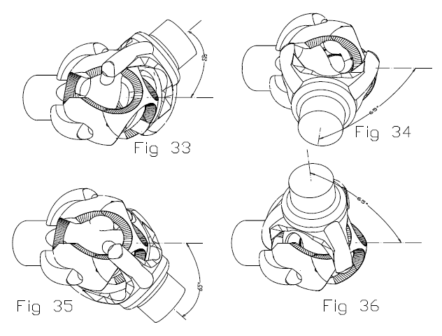
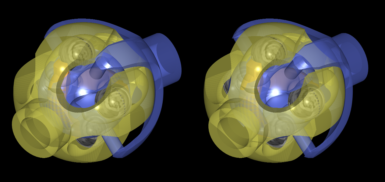
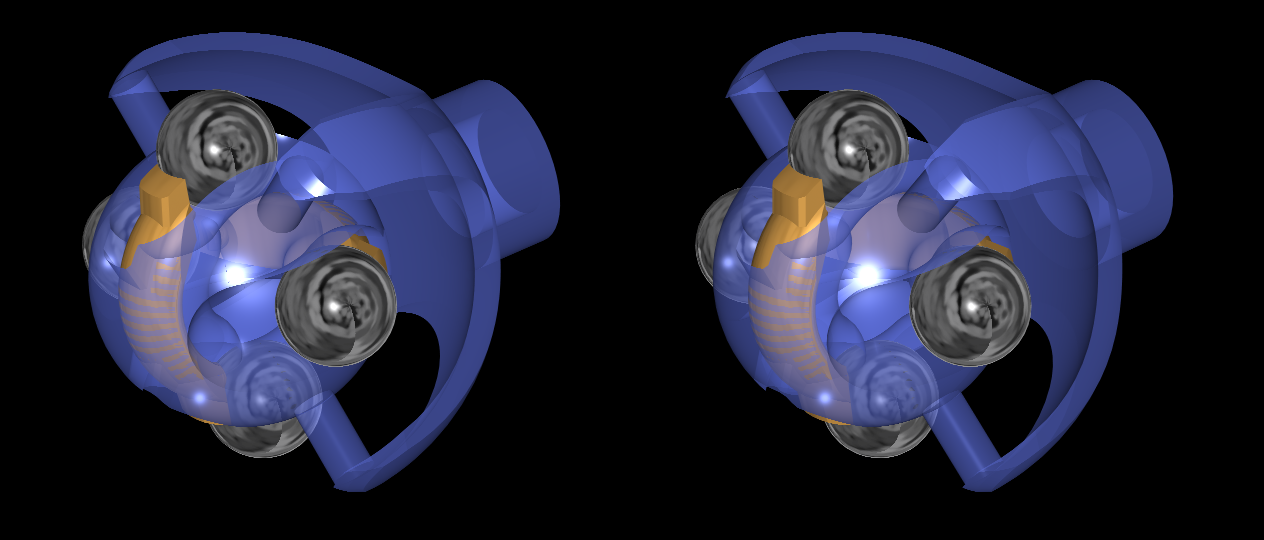
Here are two stereoscopic drawings of a PatBalDan CVJ comprising four balls and two seesaws:

Image

Image

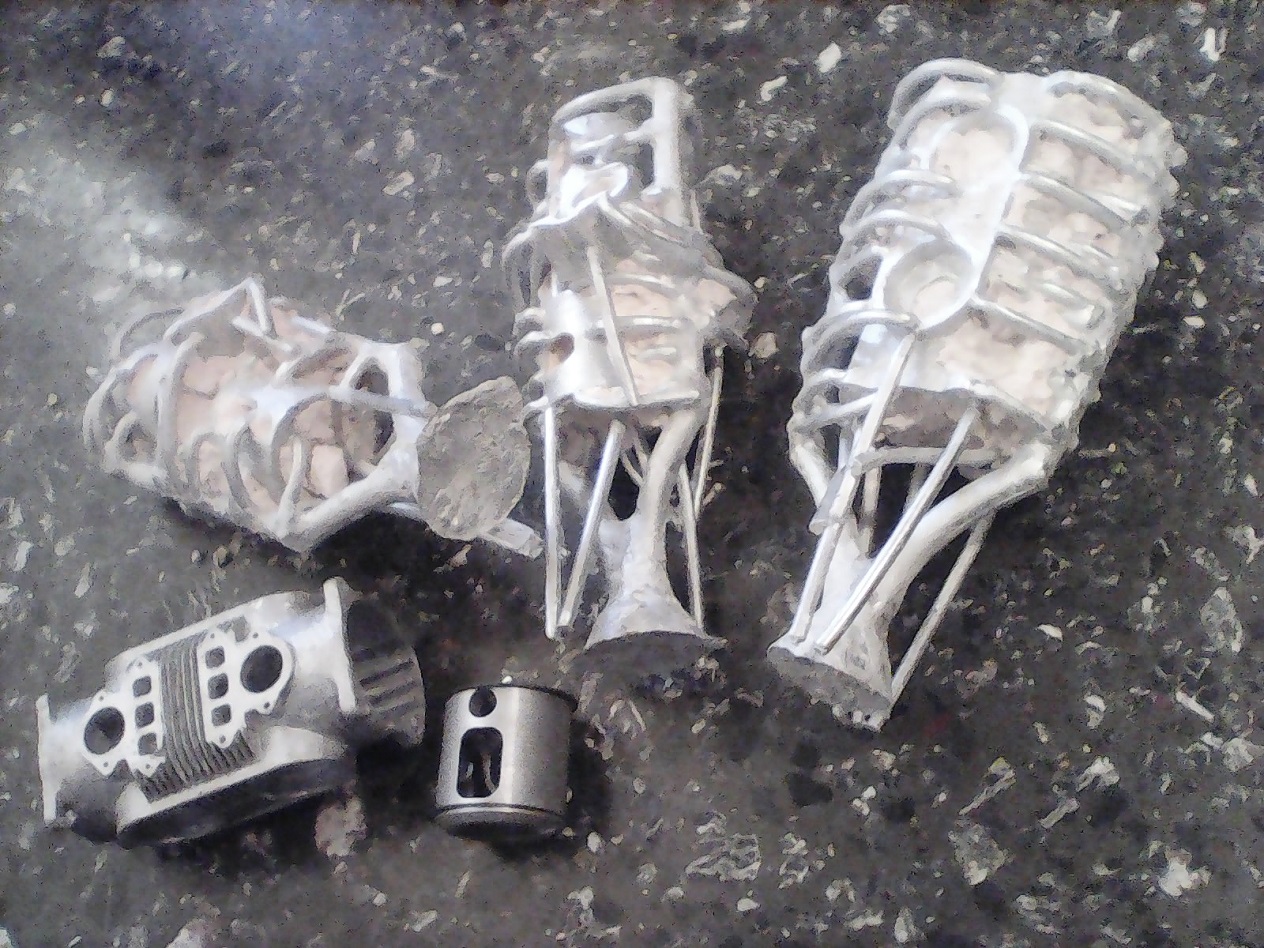
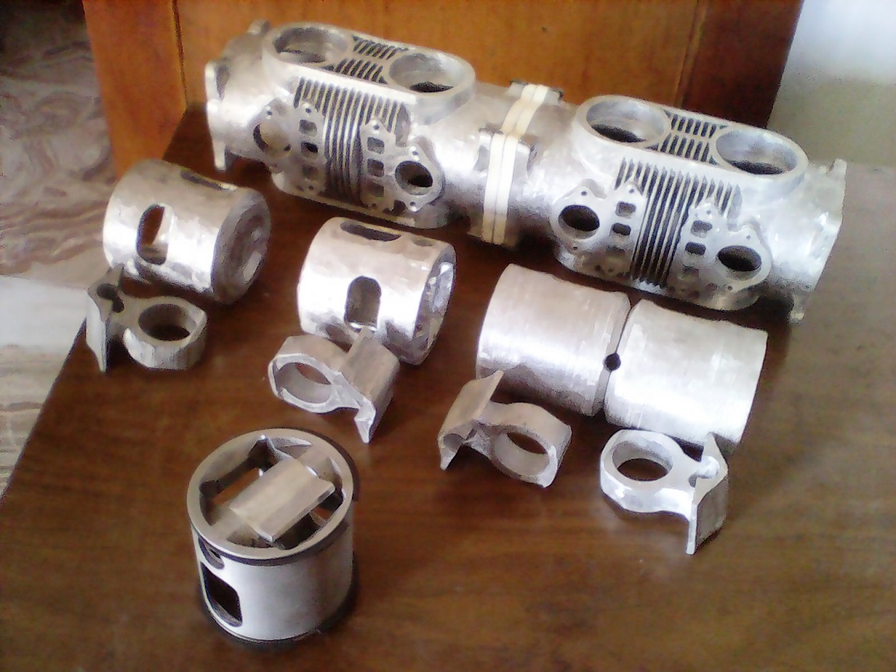
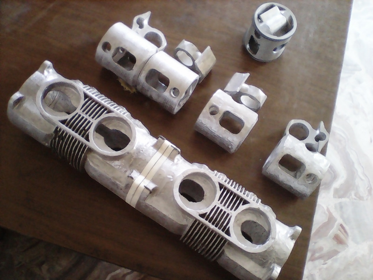
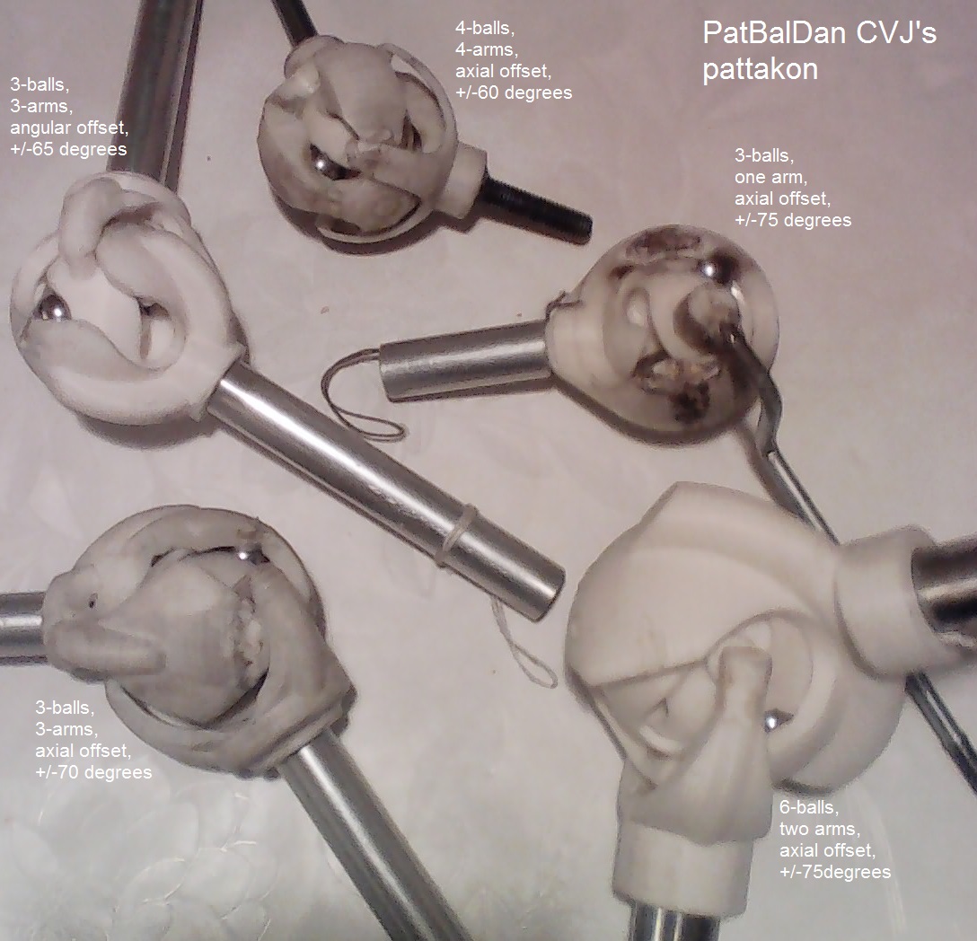
And here is a photo of five functional 3D-printed PatBalDan prototypes:

Image


For more: http://www.pattakon.com/pattakonPatBalDan.htm

Thanks
Manolis Pattakos

PhillipM
385
Joined: 16 May 2011, 15:18
Location: Over the road from Boothy...

Re: 2 stroke thread (with occasional F1 relevance!)

Post

No, that's the state of the art for *production* joints that are usable - I have joints on my car that go beyond 60 degrees, they are common in off road racing. They are also noisy and wear like hell and have to be oversized to cope with the stress.
One of your designs at the same operating stress would be absolutely huge.

manolis
107
Joined: 18 Mar 2014, 10:00

Re: 2 stroke thread (with occasional F1 relevance!)

Post

PhillipM wrote:
15 Feb 2019, 02:09
No, that's the state of the art for *production* joints that are usable - I have joints on my car that go beyond 60 degrees, they are common in off road racing. They are also noisy and wear like hell and have to be oversized to cope with the stress.
Thank you PhillipM
Any drawings or photos of the joints you have on your car?

PhillipM wrote:
15 Feb 2019, 02:09
One of your designs at the same operating stress would be absolutely huge.
As NTN claims for their TUJ cvj (that with the "Super High Operating Angle of 54 degrees"):

1. Maximum operating angle: 54 degrees
2. Functions (strength and durability): equivalent to those of conventional fixed CVJs.
3. Transmission of torque is possible even at an operating angle of 54 degrees.

Image

Which is/are the weak point(s) you see in the PatBalDan design?

As I see it,
the absence of oscillations, i.e. of dynamic / impact loads (because the PatBalDan is a 100%"constant velocity" joint, i.e. it maintains the 1:1 transmission ratio at all angles),
the fewer but larger balls that can undergo heavier loads than the smaller balls of the conventional mass-production CVJs,
and the "line contact" versus the "point contact" of the conventional balls with their cage,
talk for better reliability, less wear, less noise.

Thanks
Manolis Pattakos

Pinger
9
Joined: 13 Apr 2017, 17:28

Re: 2 stroke thread (with occasional F1 relevance!)

Post

PhillipM wrote:
15 Feb 2019, 02:09
. They are also noisy and wear like hell
What lubricant are you using?

PhillipM
385
Joined: 16 May 2011, 15:18
Location: Over the road from Boothy...

Re: 2 stroke thread (with occasional F1 relevance!)

Post

Millers Hi-Mol, about the best we've found so far.

Pinger
9
Joined: 13 Apr 2017, 17:28

Re: 2 stroke thread (with occasional F1 relevance!)

Post

PhillipM wrote:
15 Feb 2019, 20:57
Millers Hi-Mol, about the best we've found so far.
Where in the world are you?

manolis
107
Joined: 18 Mar 2014, 10:00

Re: 2 stroke thread (with occasional F1 relevance!)

Post

Hello all.

The following drawing shows the one shaft of a PatBalDan side-by-side with the NTN-TUJ:

Image

For the same external dimensions, the balls of the PatBalDan are substantially larger.


Here is the “cage” (“cage” in the meaning that it keeps permanently the ball centers on a plane passing through the center of the joint) of the above “angular offset” PatBalDan:

Image

With angular offset, the centers of the balls remain at constant distance from the center of the joint, while with “axial offset” the distance of the centers of the balls from the center of the joint vary during a rotation of the shafts.

In the above “cage”, an unconventional and interesting characteristic is that the balls keep “linear contact” with their “cage”, while in the “axial offset” CVJs the balls cannot help “point contact” with their cage.

The fewer but larger balls, the constant distance of the ball centers from the joint center and the “linear contact” talk for increased torque capacity and lower noise.

Thanks
Manolis Pattakos

manolis
107
Joined: 18 Mar 2014, 10:00

Re: 2 stroke thread (with occasional F1 relevance!)

Post

Hello all.

Today it is published the US10,221,925 patent for the PatTra CVT (Continuously Variable Transmission):

Image

The complete patent document is at http://www.pattakon.com/PatTra/US_10221925_PatTra.pdf

More at: https://www.pattakon.com/pattakonPatTra.htm

Thanks
Manolis Pattakos

Pinger
9
Joined: 13 Apr 2017, 17:28

Re: 2 stroke thread (with occasional F1 relevance!)

Post

Congrats Manolis - there's some clever thinking in there.

manolis
107
Joined: 18 Mar 2014, 10:00

Re: 2 stroke thread (with occasional F1 relevance!)

Post

Hello all.

First cast OPRE Tilting parts:

Image

Image

Image

Hopefully they will withstand the loads.

For more: https://www.pattakon.com/GoFly/index.html , https://www.pattakon.com/pattakonPatTol.htm, https://www.pattakon.com/pattakonTilting.htm

Thanks
Manolis Pattakos

Post Reply