2 stroke thread (with occasional F1 relevance!)

All that has to do with the power train, gearbox, clutch, fuels and lubricants, etc. Generally the mechanical side of Formula One.
manolis
manolis
107
Joined: 18 Mar 2014, 10:00

Re: 2 stroke thread (with occasional F1 relevance!)

Post

Hello Coaster.

You write:
" I dont believe one cancels the other, it still exists and resists sudden movements.
. . .
Every clue shared by Manolis is all we can go by, i dont believe he is here for help or advice."


Gyroscopic rigidity and “real time” Control

It will take no more than 10 seconds of your time to get it.

Go at the second 19 of the following video:


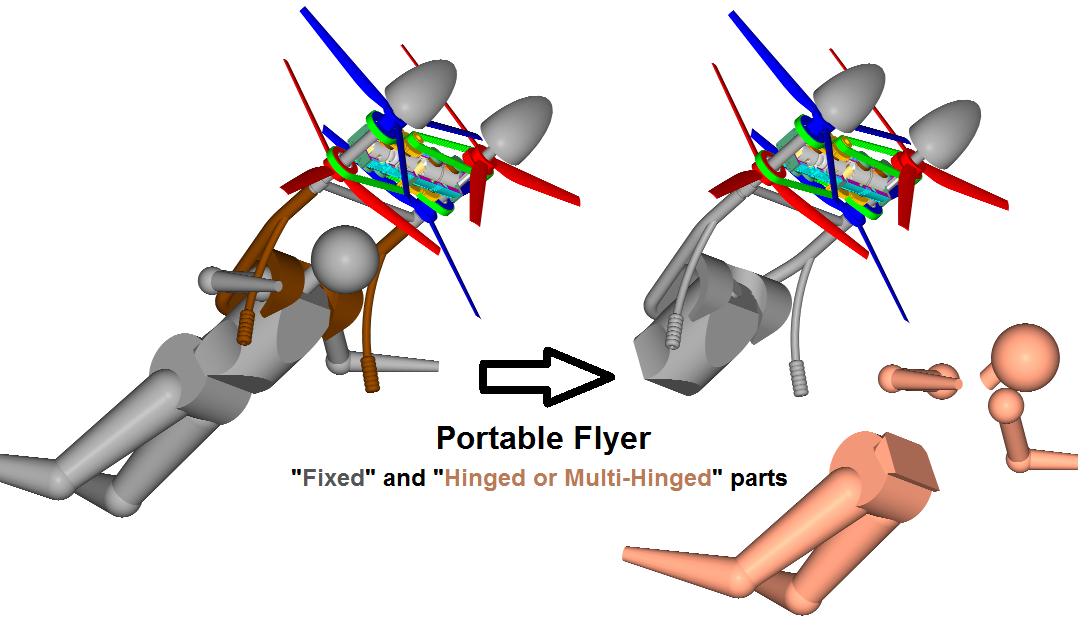
The two flywheels (think of them as the propellers of a personal flying device) spin at the same direction.

At the second 21 the guy secures on the set of the two rotating flywheels an eccentric weight (think of it as the body of the pilot who rides the personal flying device).

Despite the eccentric weight that applies a torque that tries to turn from horizontal to vertical the plain defined by the two rotation axes, the plain remains horizontal.
No matter how much the pilot will try, the response to the commands of the pilot will be so slow that there is no real control: the pilot will start a maneuver “today”, and the maneuver will complete “tomorrow” (i.e. very slowly).


Now go at the second 35 of the video.

The two flywheels (think of them as the propellers of the Portable Flyer) spin at opposite direction (they counter-rotate).

At the second 37 the guy secures on the set of the two counter-rotating flywheels the same eccentric weight, at the same eccentricity (think of it as the body of the pilot of the Portable Flyer).

The plain defined by the two rotation axes turns from horizontal to vertical immediately and oscillates freely as if the flywheels were stopped (not spinning).


Quote from https://www.pattakon.com/pattakonFly.htm
  • . . .
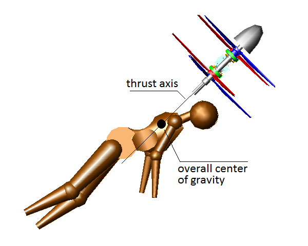
    With the symmetric counter-rotating propellers (and crankshafts), the total "gyroscopic rigidity" is zero, i.e. the rider can "instantly" (as instantly as with the propellers stopped) vector the thrust to the desirable direction..
    . . .
    The above make "a true neutral propulsion unit": neither vibrations, nor reaction torque, nor gyroscopic rigidity; only a force that can "instantly" and effortlessly be vectored towards the desirable direction.

    As aerodynamic "controls" the rider / pilot can use his legs, hands and body, just like the wing-suiters do. A wing-suit fits with the Portable Flyer, especially for long flights and fast aerobatics.

The need for zero gyroscopic rigidity (that allows instant control over the flight) is predicted by physics / maths (i.e. by the theory), and is demonstrated by the experiment in the video.

What else you need to be convinced?


Just read this post "open minded"; and if you still cannot get it, let me know what exactly you can't get.

Thanks
Manolis Pattakos

User avatar
PlatinumZealot
551
Joined: 12 Jun 2008, 03:45

Re: 2 stroke thread (with occasional F1 relevance!)

Post

Lets say the gyro effect is zero.. Even then the issue i see with his design is all that mass still is difficult to pivot because its distance from the riders CoG. This distance cannot be changed of course.. But we can change other things..

Say you are hanging in a harness tied from the upper shoulders to some fixed point overhead. (like the PF).

To pitch yourself foward you have to lift your legs to shift your CoG slightly forward to shift the stable position. This is going to need some core strength! You would need to have the fitness of a gymnast. Lifting of the legs so many times flying into a stiff wind you will get tired really fast. You will need abdominal muscles stacked like a comic book super hero.

To remedy this I am thinking about a swing set... As a child on the swingset i had good body control.. Because my upper body was free to move. I could move BOTH my upper body and and lower body to shift my CoG even more and use less strength to do so. So saying this I would suggest that Manolis examines a design where the upper body can move separate from the vehicle. And put the connection point down more towards the waist.. And a handle bar from above from ghe machine. The vehicle now rides like you do a swing set except with handles from above.

What do you think?


Simple pendulum (portable flyer) tension si the thrust... Operator hard to control once take off


Versus waist mounted... You will add some handles from above directlty to the machine though.

Go to time 1:10 to see how much more motion you get when your upper body is free.
🖐️✌️☝️👀👌✍️🐎🏆🙏

manolis
manolis
107
Joined: 18 Mar 2014, 10:00

Re: 2 stroke thread (with occasional F1 relevance!)

Post

Hello all.

Gyroscopic rigidity and internal loading.

While the pilot can effortlessly vary the direction of the rotation axes of the propellers of the Portable Flyer, internally they are created heavy loads.

Why?

While the gyroscopic rigidity of each pair of counter-rotating propellers is zero:

Image

each propeller alone has a significant gyroscopic rigidity requiring strong forces in order its rotation axis to change direction (the faster the change of the direction (and the higher the rpm), the stronger the required forces).

These forces load the shaft whereon the spinning propeller is rotatably mounted, and the structure whereon the shaft is supported.
  • Quote from https://www.pattakon.com/GoFly/DTR_1.pdf (at https://www.pattakon.com/GoFly/index.html )

    Each engine comprises:
    a casing (actually a strong pipe ~10’’ long and ~5’’ external diameter), with a cylinder liner formed into and along the casing; (securing the casings of the two engines “coaxially”, it is formed the backbone of the PORTABLE FLYER, which is actually an inflexible pipe of ~20’’ long, ~5’’ external diameter).
The above “inflexible” pipe (which is nothing but the two OPRE Titling engine casings (or cylinders) bolted with each other, and which adds no weight to the Flying Device) is the strongest part of the Portable Flyer and takes the abovementioned heavy internal loads without significant deformation.

Thanks
Manolis Pattakos

gruntguru
gruntguru
563
Joined: 21 Feb 2009, 07:43

Re: 2 stroke thread (with occasional F1 relevance!)

Post

PlatinumZealot wrote:
02 Oct 2020, 06:01
So saying this I would suggest that Manolis examines a design where the upper body can move separate from the vehicle. And put the connection point down more towards the waist..
Close.
Moving the connection point (supporting the weight of the pilot) down is a good idea. The ideal location for the pivot however, is above the CG of the flyer (everything not including the pilot). This can be done with a virtual pivot or instant centre. Locating the pivot here ensures the mass of the flyer does not tend to topple in the absence of pilot input.
je suis charlie

NathanE
NathanE
3
Joined: 31 Mar 2017, 07:49

Re: 2 stroke thread (with occasional F1 relevance!)

Post

PlatinumZealot wrote:
02 Oct 2020, 06:01

What do you think?


Simple pendulum (portable flyer) tension si the thrust... Operator hard to control once take off

https://youtu.be/4LHa9w6aX5E

Versus waist mounted... You will add some handles from above directlty to the machine though.

Go to time 1:10 to see how much more motion you get when your upper body is free.
https://youtu.be/GUQ41uQwyZs
These are clearly fake videos made in Photoshop by promoters of the pendulum rocket fallacy.

uniflow
uniflow
36
Joined: 26 Jul 2014, 10:41

Re: 2 stroke thread (with occasional F1 relevance!)

Post

manolis wrote:
01 Oct 2020, 04:57
Hello Uniflow.

I think you mean G (and not H) as the “intake to the top transfer ports" (H seems to be the top end of the cylinder bore).

https://www.pattakon.com/tempman/Uniflow_OP_175cc_1.png


More guesses / questions:
  • One only spark plug?

    The two crankcases (the hot (at top) and the cold) communicate freely through the G (unless you have another rotary valve, at the other side of the bottom crankcase, to control the "top" transfer ports).

    The top (or exhaust) crankshaft is advanced for some degrees (Hugo Junkers used 11 degrees phase difference in his Diesel Opposed Pistons) relative to the bottom crankshaft to give asymmetric timing? If yes, shouldn’t you take the power from the exhaust crankshaft to reduce the loading on the synchronizing gearing?

    What synchronization gearing is used between the two crankshafts? Without covers I suppose it is made by sprockets / toothed belt.

    A photo of the engine from the other side of the cylinder would help. Or some drawings.

Note: If you are thinking of patenting something (to protect your Intellectuall Property), don't show it and don't explain it.

Thanks
Manolis Pattakos
Yes perhaps G.
Sparkplug / plugs or not, might be a form of HCCI, can't say.
Tooth belt for the moment.
Only 6 degrees out of phase.
Top and bottom crankcases, top one uses a reed for induction. Cases joined? can't say.
View the other side of the cylinder, sorry manolis I can't do that either.
The pistons are composite construction,

User avatar
coaster
16
Joined: 30 Jun 2012, 05:10

Re: 2 stroke thread (with occasional F1 relevance!)

Post

20 years ago i had a killer aspin design like yours, no patent, i just could not figure out how to open and close it efficiently.
Now i think about it, you chanced upon a simliar idea but used reed valves to control exhaust pressure at overlap.
Well done, i should have stayed the course and you have.
Get a patent.

Rodak
Rodak
35
Joined: 04 Oct 2017, 03:02

Re: 2 stroke thread (with occasional F1 relevance!)

Post

Every clue shared by Manolis is all we can go by, i dont believe he is here for help or advice.
We are merely observers of his, thing.
Yep. A few pages back manolis asked for some aerodynamic help; I asked him some basic questions and never got any response. An articulated doll test rig would be pretty easy to build and would help show if this 'flyer' was actually controllable. Words and pictures don't replace data.....

I think the biggest problem he has is his insistence on having a rigid mount to the body. A ways back manolis said that if there were failure of one propeller all the pilot had to do was shift his weight sideways, but with the mounting system he has that is impossible to do.

User avatar
nzjrs
60
Joined: 07 Jan 2015, 11:21
Location: Redacted

Re: 2 stroke thread (with occasional F1 relevance!)

Post

Rodak wrote:
02 Oct 2020, 16:19
Every clue shared by Manolis is all we can go by, i dont believe he is here for help or advice.
We are merely observers of his, thing.
Yep. A few pages back manolis asked for some aerodynamic help; I asked him some basic questions and never got any response. An articulated doll test rig would be pretty easy to build and would help show if this 'flyer' was actually controllable. Words and pictures don't replace data.....

I think the biggest problem he has is his insistence on having a rigid mount to the body. A ways back manolis said that if there were failure of one propeller all the pilot had to do was shift his weight sideways, but with the mounting system he has that is impossible to do.
Yip, me too :?:. A nice list of things to measure so we could do something quantitative. Whats funny is that PZ then says the same things and shows some nice trapeeze videos - if we could get Manolis to take some photos/videos of himself hanging from a mocked up flyer and moving is limbs about we could derive some mass/torque information from his posture change and actually speak about something new.

This thread repeats itself about every 20 pages it seems.

Oh well, Honda is out of F1. That's the story of the day. :arrow:

User avatar
coaster
16
Joined: 30 Jun 2012, 05:10

Re: 2 stroke thread (with occasional F1 relevance!)

Post

Yes, its bummer Honda has quit again, we are in a deep recession due to covid19 though.
I wish I could build the pf with servo control and drone stabilisation, its begging to be done and all the nonsensical rubbish of rigid control guided by lips, eyelids and leg swinging.
Arrrrgghh!!!!!

manolis
manolis
107
Joined: 18 Mar 2014, 10:00

Re: 2 stroke thread (with occasional F1 relevance!)

Post

Hello PlatinumZealot

You write:
“ Lets say the gyro effect is zero.. Even then the issue i see with his design is all that mass still is difficult to pivot because its distance from the riders CoG. This distance cannot be changed of course.. But we can change other things..”


All this mass (the gray colored assembly, top-right):

Image

needs not to pivot.
The rest masses (beige colored, right bottom) do the job.

If you displace / pivot the hip, head, limbs relative to the above assembly, then you have full “weight displacement control”.

To lift your arm, to move your leg, to bend your spine are normal simple easy motions.


You also write:
“Say you are hanging in a harness tied from the upper shoulders to some fixed point overhead. (like the PF):
To pitch yourself foward you have to lift your legs to shift your CoG slightly forward to shift the stable position. This is going to need some core strength! You would need to have the fitness of a gymnast. Lifting of the legs so many times flying into a stiff wind you will get tired really fast. You will need abdominal muscles stacked like a comic book super hero."


It is not the same.

When you are free in the air (abutting nowhere but in air) there is not pivot point.

What there is, is a thrust axis (it is the vector of the resultant force from the propellers).
And this thrust axis passes, from the beginning, close by the overall center of gravity:

Image

The pilot needs not to be a gymnast to apply the necessary forces.
And the duration of a correction is short (maybe less than a second) before the pilot restores to its normal posture.

At flight the only you can do (and the only you need to do) is to displace the overall center of gravity relative to the thrust axis by displacing your limbs, head and hip relative to the “back / torso / Portable Flyer” assembly, i.e. relative to the thrust axis.

That simple.


Forget the pivot point in the air.
It is a fallacy.
There is no such thing.
The guy who flies in the air is not a pendulum.
A pendulum needs a pivot point to provide the necessary reaction force.
This is what the Pendulum Rocket Fallacy explains.


You write:
“To remedy this I am thinking about a swing set... As a child on the swingset i had good body control.. Because my upper body was free to move. I could move BOTH my upper body and and lower body to shift my CoG even more and use less strength to do so. So saying this I would suggest that Manolis examines a design where the upper body can move separate from the vehicle. And put the connection point down more towards the waist.. And a handle bar from above from ghe machine. The vehicle now rides like you do a swing set except with handles from above.
What do you think?”


and

Gruntguru writes:
” Moving the connection point (supporting the weight of the pilot) down is a good idea. The ideal location for the pivot however, is above the CG of the flyer (everything not including the pilot). This can be done with a virtual pivot or instant centre. Locating the pivot here ensures the mass of the flyer does not tend to topple in the absence of pilot input.”


In a swingset there is a pivot.
In the air there is no pivot.
When you fly, what there is, is a thrust axis.
The thrust axis, the air and your body posture are the only things you have .

The only that matters, in the air, is the eccentricity of the overall center of gravity from the thrust axis.

What really is the “connection point” mentioned?

The “Portable Flyer / Back / Torso” assembly has:
a “connection point” with the neck / head,
another different “connection point” with the left arm,
another different “connection point” with the right arm,
another different “connection point” with the hip,
each hand has its own “connection point” with the respective arm,
each leg has its own “connection point” with the hip, each foot . . .

Thanks
Manolis Pattakos

Rodak
Rodak
35
Joined: 04 Oct 2017, 03:02

Re: 2 stroke thread (with occasional F1 relevance!)

Post

Yep. How about some actual data re c.g., weight, attachment, etc. etc. so we can analyze stuff? I can make pictures that show exactly the opposite of yours and they are just as valid. Until you provide numbers.

manolis
manolis
107
Joined: 18 Mar 2014, 10:00

Re: 2 stroke thread (with occasional F1 relevance!)

Post

Hello Rodak.

You write:
“How about some actual data re c.g., weight, attachment, etc. etc. so we can analyze stuff? ”


Start with the analysis of the free inertia force, moments and torque of the conventional even-firing three-cylinder in-line engine.

If you achieve it, continue with the “two up, one down” straight-three of Uniflow and present their differences, if any.


With the Balance program, at the Teaching section of the www.pattakon.com (written dozens of years ago in QuickBasic / DOS environment) you can make the analysis in two minutes, you can also make the Fourier Analysis of the free inertia force, moments and torque, you can also “play” with external balance shafts and can check the improvement they brink.
The Fourier Analysis is an extremely useful tool, but it is difficult to get how it works.


The above problem (vibrations and balancing of a reciprocation piston engine) is a million times simpler than the analysis of the slow walking of a person.

And the analysis of the slow walking of a person is a million times simpler than the analysis of the flight of the wind-dancer:


Each finger of the wind-dancer plays its own significant role on her flight.


In any case, if you insist to make some analysis of the Portable Flyer, choose by your own the “c.g, weight, attachment etc, etc” and proceed.

Thanks
Manolis Pattakos

User avatar
nzjrs
60
Joined: 07 Jan 2015, 11:21
Location: Redacted

Re: 2 stroke thread (with occasional F1 relevance!)

Post

He's your problem now PZ.

NathanE
NathanE
3
Joined: 31 Mar 2017, 07:49

Re: 2 stroke thread (with occasional F1 relevance!)

Post

nzjrs wrote:
03 Oct 2020, 10:19
He's your problem now PZ.
Groundhog day :lol: