Honda Power Unit Hardware & Software

All that has to do with the power train, gearbox, clutch, fuels and lubricants, etc. Generally the mechanical side of Formula One.
63l8qrrfy6
368
Joined: 17 Feb 2016, 21:36

Re: Honda Power Unit

Post

I am sure that the K is very well torsionally isolated from the ICE, most likely damped as well (Cosworth KERS was). As such I don't expect any of the low frequencies to be transmitted over to the crank.

The crank train first torsional frequency is about an order of magnitude higher anyway so it's unlikely to excite anything with 40 hz.

Tommy Cookers
620
Joined: 17 Feb 2012, 16:55

Re: Honda Power Unit

Post

sometimes I don't know whether a post is in broad agreement with mine or in broad disagreement ......

the K must draw from outside mechanical energy equivalent to c.120 kW to generate electrical energy at 120 kW
unless people saying that mechanical energy comes from bleeding down the K rpm and not from the ICE

the K may have a somewhat compliant connection to the crankshaft but it's not a freewheel or a slipper or a clutch
ie surely its compliance range is less than one crankshaft revolution ?

FvtecA
3
Joined: 11 May 2017, 18:17

Re: Honda Power Unit

Post

muramasa wrote:
20 Mar 2018, 22:32
 
"(MGU-K deployment's) contribution to the lap time is big, so the concept of deploying MGU-K as much as possible is unchanged. In 2016, there was abundant energy even if MGU-K assist is (fully) used, so we were able to make e-boost of MGU-H. But this year it's short of energy, so no choice but to stop using e-boost."

MGU-K -> ES: 2MJ/lap
ES -> MGU-K: 4MJ/lap
MGU-H <-> ES: Unlimited

"What's called "extra harvest" is about taking advantage of unlimited exchange of energy between MGU-H and ES"

  MGU-K -> MGU-H -> ES instead of MGU-K -> ES

"it's only 2MJ/lap with MGU-K -> ES, but with MGU-K->MGU-H->ES, you have extra few MJ added on top of the original 2MJ"


[Spa Quali telemetry comparison between 2016 and 2017]
"Belgium is a circuit where there was shortate of energy for deployment, so even in 2016 we were not able to use e-boost. "
- In 2017 MGU-K deployment starts at earlier point than 2016, so deployment runs out in the middle of T10 and T12.
- In 2016, driver was lifting throttle a bit in T15 but in 2017 it's full throttle.
- At the full throttle section from Eau Rouge to Kemmel, they are able to make full deployment throughout the section in both 2016 and 17.


MGU-K recovery is done not only at braking but also during acceleration. During the acceleration phase, turn ICE more than driver's pedal input and use the excess power of ICE to turn MGU-K for harvest. Called Partial Harvest at Honda.


[Telemetry comparison between Extra Harvest on and off]
  Under braking (where MGU-K graph goes to the bottom = harvesting), MGU-H graph goes up and down repeatedly and rapidly, so graph looks like its area filled almost entirely during the phase or quake tremor graph.


"The idea itself (of Extra Harvest) already existed at the point of 2016, but there was MGU-H durability to consider, so we were contemplating when to introduce it by assessing the durability/performance balance. We trialed it at Belgium GP 2017, before fully introducing it from Italy onward."

  - During Extra Harvest, MGU-H is busy switching between harvest and deployment back and forth rapidly in 20~40Hz range.

"During the acceleration phase, normally MGU-H makes a bit of deployment in order to keep boost pressure, but when conducting Extra Harvest, you use MGU-H by switching on and off. The reason is that you regenerate the amount of "On" (by using energy generated by MGU-K). You deploy MGU-H and give it inertia energy, then recover it at once."

"MGU-H handles not only the exchange of energy but also controls boost pressure. As a matter of course, we make Extra Harvest in a way that boost control is not affected."

  - As a result of Extra Harvest, no more running out of deployment

"This 2MJ and 4MJ setting for MGU-K is well thought of in order to prompt elaboration of its use, also it's fine regulation in terms of encouraging makers to focus on MGU-H in development."

"In production cars, manufacturers have the type of hybrid system that assist the drive directly, but not the type that makes heat regeneration. Therefore FIA opened and left that particular area so that makers can focus on its development, I reckon."

"(What if full throttle period increase even further in 2018?) It's about balance between ICE power and MGU-H recovery. We must get that right."
This is really interesting.

I remember thinking why McLaren was so easily overtaken by everyone in Spa (including I think by a Toro Rosso), but were constantly threatening to overtake Toro Rosso in Monza, when one would think that Monza would be even worse. This seems to explain why.

johnny comelately
110
Joined: 10 Apr 2015, 00:55
Location: Australia

Re: Honda Power Unit

Post

Tommy Cookers wrote:
21 Mar 2018, 12:15
roughly it's similar to 1 or 2 cylinders cutting in out then in 20 or 40 times a second

1 if at eg 12000 ICE rpm
2 if at eg 6000 ICE rpm

200 Nm K torque (referred to crankshaft) at any ICE rpm from 5710 roughly to 15000

but 1 or 2 cylinders cutting in and out at 20-40 times a second is ok - but eg 2 - 4 times a second is mechanically embarassing
like the difference between driving your car at 30 mph in top gear and driving it at 3 mph in top gear
Actually Tommy (and probably booked by the correct thread police here, but I have 1 or 2 points left on my licence) that brings in a larger matter here of traction under acceleration and different factors that affect it.
in this video - https://www.youtube.com/watch?v=J1JuxgiPvz0 - you will hear Montoya scrabbling for traction and some would say its on the limit and cannot be improved, but I say it's worth a shot.
If it was drags you might with play clutch, tyre pressures, then maybe dampers depending on what's in the ballpark.
And remembering this is 4 wheels; 1WD is even more sensitive , eg, harleys vs hondas at the flatracks, where originally (Jay Springsteen days) crankshaft behaviour was the determiner for traction.
I am guessing ( i havent got enough science to bite me) with higher RPM the the torque pulses are less of an issue.
Any thoughts on curing Mr Montoya's issue.

User avatar
henry
324
Joined: 23 Feb 2004, 20:49
Location: England

Re: Honda Power Unit

Post

Mudflap wrote:
21 Mar 2018, 12:51
I am sure that the K is very well torsionally isolated from the ICE, most likely damped as well (Cosworth KERS was). As such I don't expect any of the low frequencies to be transmitted over to the crank.

The crank train first torsional frequency is about an order of magnitude higher anyway so it's unlikely to excite anything with 40 hz.
Am I missing something here? Surely it’s the crank that drives the K so it has to experience the variations in torque, no matter how damped or torsionally isolated?
Fortune favours the prepared; she has no favourites and takes no sides.
Truth is confirmed by inspection and delay; falsehood by haste and uncertainty : Tacitus

Tommy Cookers
620
Joined: 17 Feb 2012, 16:55

Re: Honda Power Unit

Post

[quote="johnny comelately"]
...... a larger matter here of traction under acceleration and different factors that affect it.
......this is 4 wheels; 1WD is even more sensitive , eg, harleys vs hondas at the flatracks, where originally (Jay Springsteen days) crankshaft behaviour was the determiner for traction.
I am guessing ( i havent got enough science to bite me) with higher RPM the the torque pulses are less of an issue.
Any thoughts on curing Mr Montoya's issue.[/quote]

fwiw I am a big bang sceptic
because imo the torque pulses won't reach the tyre contact patch
(is someone saying Springsteen used bike with near-simultaneous firing not the near-even firing intervals ex-factory ??)
and because if BB worked a BB-engine effect could be engineered in the transmission driven by a non-BB engine

but F1 gets a wheelslip alleviation term from the K in acceleration and braking (the term according to the K and ICE sizes)

the K synchronous machine needs its excitation pulses applied at exact points relative to the point in revolution of the rotor
so that it can develop its mapped torque output or electrical output
it continuously measures its rotational position, producing an rpm signal compared with produced rpm demand continuously

any eg wheelspin when K motoring is mapped will increase K rpm and K motor action will rapidly reduce in torque or reverse it
similarly wheel locking when K generation is mapped is resisted

User avatar
godlameroso
309
Joined: 16 Jan 2010, 21:27
Location: Miami FL

Re: Honda Power Unit

Post

Tommy Cookers wrote:
21 Mar 2018, 18:41
johnny comelately wrote: ...... a larger matter here of traction under acceleration and different factors that affect it.
......this is 4 wheels; 1WD is even more sensitive , eg, harleys vs hondas at the flatracks, where originally (Jay Springsteen days) crankshaft behaviour was the determiner for traction.
I am guessing ( i havent got enough science to bite me) with higher RPM the the torque pulses are less of an issue.
Any thoughts on curing Mr Montoya's issue.
fwiw I am a big bang sceptic
because imo the torque pulses won't reach the tyre contact patch
(is someone saying Springsteen used bike with near-simultaneous firing not the near-even firing intervals ex-factory ??)
and because if BB worked a BB-engine effect could be engineered in the transmission driven by a non-BB engine

but F1 gets a wheelslip alleviation term from the K in acceleration and braking (the term according to the K and ICE sizes)

the K synchronous machine needs its excitation pulses applied at exact points relative to the point in revolution of the rotor
so that it can develop its mapped torque output or electrical output
it continuously measures its rotational position, producing an rpm signal compared with produced rpm demand continuously

any eg wheelspin when K motoring is mapped will increase K rpm and K motor action will rapidly reduce in torque or reverse it
similarly wheel locking when K generation is mapped is resisted
Do these mgus have stationary magnets? I'd imagine so due to being able to control the RMF speed with greater precision.
Saishū kōnā

muramasa
58
Joined: 05 Oct 2017, 16:33

Re: Honda Power Unit

Post

Mudflap wrote:
21 Mar 2018, 00:06
"Structure of Pneumatic Valve Return System has been simplified and reduced in size, contributing to lower cog"
This statement does not tie up with an earlier translated article which claimed that Honda use valvesprings.
Not sure which one but perhaps "the earlier one" was wrong translation or fake or something.

Mudflap wrote:
21 Mar 2018, 00:06
"Channel blow-by gas here (to the sub tank above plenum chamber). It has some degree of swirl structure/function inside. The key is how well you separate oil from air and let scavenge pump suck oil only."
Maybe a translation error ? The scavenge pump will always pull blowby and oil out of the crankcase. Do you mean oil pump instead ?
That's exactly what the original text says, no room for subtle nuance or translation error. Well yeah it's not strictly precise but roughly accurate, how about this: let scavenge pump return all the oil to oil tank, let scavenge pump return air back to inlet, or combine both, etc. Actually mentioning scavenge pump is not really necessary for this particular explanation, but it's in face to face colloquial and improvised conversation/exchange, so, and you get the picture anyway dont you.

Mudflap wrote:
21 Mar 2018, 00:06
It is interesting that they offer yet another explanation for MGUH bearing failures. Can't decide if it is plausible or not.
Yet another? Perhaps you (plural and general) have been given false info. There has been only sole explanation from the very beginning - MGU-H bearing burn/stuck due to blown back mist that cause MGU-H failure (breaking MGU-H itself, breaking turbo, failing its cooling system like leaking its coolant water, etc etc as a consequence), that's what Hasegawa had been explaining ever since Bahrain for Japanese press and I dont know and never heard any other explanations. When it comes to Honda there are so many false, fake and hoax stuffs somehow, so.

They had MGU-H issue since like Bahrain and that was the issue that kept plaguing them throughout the year albeit they improved on it gradually.
2017 MGU-H failures offhand:
 Bahrain - 4? units fail
 Monaco
 Canada
 Austria
 USA
(perhaps more. Spa issue was ICE, Monza was MGU-K, one or two others were gearbox btw.)

Ever since Bahrain Hasegawa had been explaining the same thing - mgu-h's bearing burn/stuck due to blown mist to compressor entering mgu-h -, and repeatedly adding more and more info bits as they encountered the issue and learned more.
To roughly summarize: They brought countermeasures almost every race, like toughening bearing and shaft in whatever way, thickening bearing, revising MGU-H cooling in many ways, revising oil system as well as separator tank. Why oil system, because the unconventional oil tank shape due to the compressor moved out of V is part of this problem too, at first the oil didn't circulate well so they increased the absolute amount of oil as well as of course revising its baffles and config as countermeasure. Then this increased oil started to do bad things to MGU-H. It didnt occur on dyno, of course they have dynamic dyno but conditions like G-load and numbers and degree of bumps that affect oil circulation vary widely depending on track and cannot be fully replicated on dyno. As you can see, it's like chain reaction and they had to spend almost whole season addressing it in symptomatic treatment style.
That's what it was about this MGU-H in 2017.


PlatinumZealot wrote:
21 Mar 2018, 02:29
The translation of the japanese article pretty much explains it. When in extra harvest mode the MGUH is alternately charging and discharging in 20Hz to 40Hz intervals.

For example: The mguk motors the mguh on the "uptick" the cycle (this may or may not add energy to help turn the compressor).

Then the remaining extra inertia of the mugh goes into charging the energy store on the "down tick" of the cycle.

This happens twenty times to forty times a second.
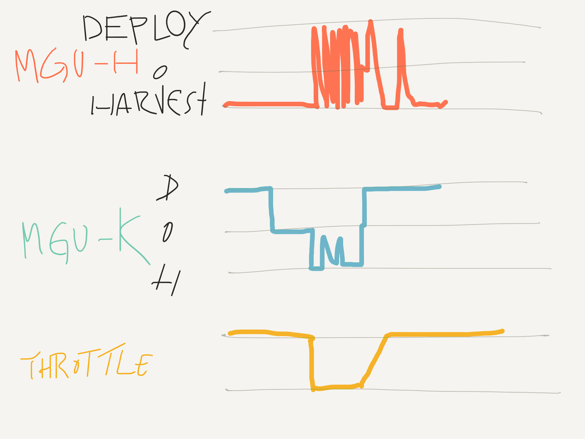
yeah, so telemetry looks like this
 - excuse me for poor diagram, but still it's roughly accurate
 - MGU-H up/down frequency is much more intense than this, leaving no blank space
 - MGU-K's spike is downshift, it's not wide=long like this actually, just an instant
 - MGU-K goes to 0 before throttle is lifted. That's about running out of deployment
 - not that all the brakings looks the same

Image


By the way, about the pop-off valve, first versions it was positioned to channel the hot compressed air back to inlet which is this demonstration PU in pictures, but later version was changed to channel the cooled air after intercooler back to inlet. I forgot to add this, maybe i'll add to the original post later.

User avatar
godlameroso
309
Joined: 16 Jan 2010, 21:27
Location: Miami FL

Re: Honda Power Unit

Post

Tommy Cookers wrote:
21 Mar 2018, 13:19
sometimes I don't know whether a post is in broad agreement with mine or in broad disagreement ......

the K must draw from outside mechanical energy equivalent to c.120 kW to generate electrical energy at 120 kW
unless people saying that mechanical energy comes from bleeding down the K rpm and not from the ICE

the K may have a somewhat compliant connection to the crankshaft but it's not a freewheel or a slipper or a clutch
ie surely its compliance range is less than one crankshaft revolution ?
Impossible to have a viscous coupling?
Saishū kōnā

User avatar
godlameroso
309
Joined: 16 Jan 2010, 21:27
Location: Miami FL

Re: Honda Power Unit

Post

johnny comelately wrote:
21 Mar 2018, 08:43
Regarding "muramasa"'s brilliant post:

"Fuel pump is positioned on cylinder head cover, same as RA616H. But the fuel line, which was placed along the ignition coils for RA616H, cannot be seen at the same location with RA617H. Therefore RA617H is not top injection.
  RA615H: side injection on inlet port side.
  RA616H: top injection
  RA617H: The author is speculating that it's side injection on exhaust port side (can be seen in pics anyways)

THROUGH TO

"We've trialed dozens of different configurations for the sub chamber, and much more than that for the injector. If you consider increasing combustion efficiency and thermal efficiency under the current reg, pre-chamber is the path you must take. Current regulation will continue until 2020. We are going to continue development of increasing combustion speed, which includes increasing compression ratio, beyond 2018."

EXHAUST SIDE injection is very effective at solving " increasing air homogeneity" in a non-traditional approach we have had great success with.
And not being of the Mahle variety with separation from the pre-combustion chamber giving far more latitude with ignition point mixture. With previous photos from "Wazari" showing a separate ingress (valve controlled?) to the multi egresses for the flames. Whilst this is very good, it is seriously constrained by the FIA rule saying only one.
If I may.
Exhaust side injectors main benefit could be fine control of fuel temperature via exhaust heat. Air homogeneity would be better translated as air dilution. Extremely interesting that they don't use a Mahle style pre-chamber, however they do use a shrouded spark plug :lol: (can't stop laughing at what mudflap called it) and the hole size and placement is critical for it to function. I guess "team Wazari" design has a valve like activated method to stratify the mixture in their flame ignition system, which comes close to, but not quite as efficient as if they had more than 1 injector, or one specifically for their flame ignition system and another for the main chamber.
Saishū kōnā

User avatar
PlatinumZealot
551
Joined: 12 Jun 2008, 03:45

Re: Honda Power Unit

Post

A pre-chamber was explicitly stated in the translation.
🖐️✌️☝️👀👌✍️🐎🏆🙏

User avatar
godlameroso
309
Joined: 16 Jan 2010, 21:27
Location: Miami FL

Re: Honda Power Unit

Post

Pre chamber sure, I mentioned that, but it's not a Mahle style separate chamber from the main combustion chamber. It's the spark plug cap type pre-chamber.
Saishū kōnā

63l8qrrfy6
368
Joined: 17 Feb 2016, 21:36

Re: Honda Power Unit

Post

henry wrote:
21 Mar 2018, 16:16
Mudflap wrote:
21 Mar 2018, 12:51
I am sure that the K is very well torsionally isolated from the ICE, most likely damped as well (Cosworth KERS was). As such I don't expect any of the low frequencies to be transmitted over to the crank.

The crank train first torsional frequency is about an order of magnitude higher anyway so it's unlikely to excite anything with 40 hz.
Am I missing something here? Surely it’s the crank that drives the K so it has to experience the variations in torque, no matter how damped or torsionally isolated?
What I am saying is that the K should not see the torsional signature of the crank - the amplitudes have to be much lower. When the K is driving, the torsional signature of the electric motor should not be seen at the crank either.

More specifically, the engine will generate the highest torsional amplitude at order 1.5 and probably the second highest amplitude at order 3. These amplitudes have to be greatly reduced by the time they reach the electric motor rotor. When the K is driving it will generate the highest torsional vibration amplitude at an order equal to half the number of poles. This amplitude will also be greatly reduced by the time it reaches the crank.

If the lowest engine speed were to be say 6000 rpm, and you'd want to isolate the 1.5th order (150 Hz at this minimum engine speed) you'd need the natural frequency of the compliant element and rotor to be 150/(sqrt(2)), say about 100 Hz (transmisibility is 1 at a frequency ratio of sqrt(2)).

Now, if the motor has 4 poles and is geared at a ratio of 3.33, it would produce the peak torsional amplitude at 666 Hz while driving. This will again be well isolated since the frequency ratio is >> 1.
Do these mgus have stationary magnets? I'd imagine so due to being able to control the RMF speed with greater precision.
They most definitely have permanent magnets on the rotor.

Impossible to have a viscous coupling?
The efficiency would be poor and it would be bulky but it would make for a decent damping device.
I am not sure it would be possible though since rules specify a constant speed ratio between crank and K.

User avatar
godlameroso
309
Joined: 16 Jan 2010, 21:27
Location: Miami FL

Re: Honda Power Unit

Post

So then a gear with belville springs, sort of like the spring system on a clutch disk? And then this can double as the crank torsional damper as well.
Saishū kōnā

63l8qrrfy6
368
Joined: 17 Feb 2016, 21:36

Re: Honda Power Unit

Post

If you really need damping, then yes it would work but I don't think it can double as a crank damper.
It is also possible to have the damper on the back of the motor too.

A damper is most efficient where the amplitude of vibration is highest (also known as an anti node). On a conventional engine with a high inertia flywheel the anti node is away from the flywheel on the nose of the crank hence the damper always sits at the front. In F1 camshafts the highest displacement is always at the rear of the cam so the dampers have invariably sat at the end.

In current F1 engines the effective inertia at the crank nose is quite high due to the K gearing, while the flywheel doesn't really exist so my hunch (well a bit more than that - I know that the cossy v8 had a rear damper - and 13 others!) is that crank dampers would be better placed at the rear of the engine.

Post Reply