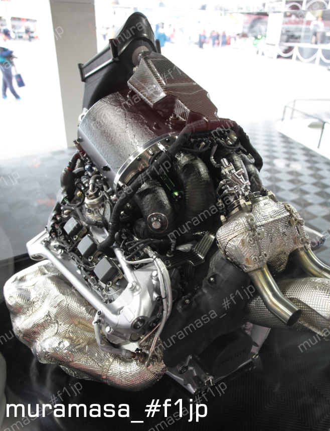
Honda's 2017 Season F1 Power Unit RA617H featured on Japanese magazine called Motor Fan published couple months ago
https://www.amazon.co.jp/Motorsport%E3% ... EKG1AM95JR
I'm not following this forum, so maybe this has been done already, I dont know, but I imagine different translator can be of some use so here it is anyway.
- I use my own pictures
- " " parts are engineers quotes
===================================
Engineers interviewed
Yoshiyuki Ugomori
Mitsuaki Yoshimoto
(same as 2016 Edition featuring RA616H)
RA616H -> RA617H
- By moving TC out of V, inlet layout is now optimal form. However oil tank was affected negatively instead.
- piping position has been changed from the right side of the car to the left side. Rotation direction of TC has been inverted as well.
"2015's and 2016's were designed under the same packaging concept basically. For 2017's, we changed the concept drastically as you can see."
"2015's unit has been designed by prioritizing packaging under the size zero concept. As a result, there were quite a bit of areas that have been restricted by it, but 2017's has been re-packaged as it should be."
"This is a racing engine, so weight and cog are crucial factors. With 2017 unit, we have progressed quite a bit in these areas as well. The unit gains weight gradually through the season as you improve its reliability. In that sense, we were not able to reach our targeted weight in 2016."
- With RA617H, they were able to shed several kilograms with the engine alone, reaching the target weight.
"Structure of Pneumatic Valve Return System has been simplified and reduced in size, contributing to lower cog"
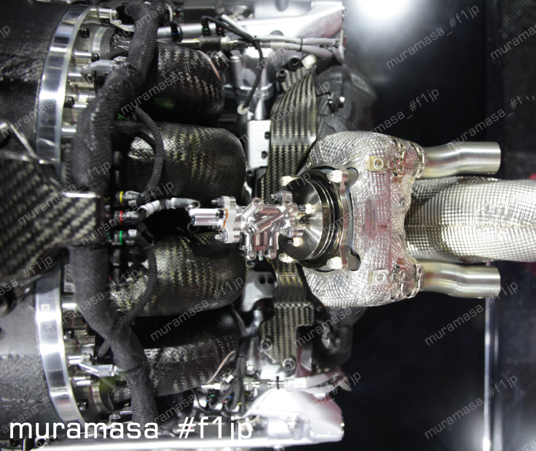
Moving turbo outside of V:
- to increase the size of compressor
- to move large components sitting there out of it, which enabled inlet design easier
- to lower the cog
- to optimize inlet layout
- to increase boost pressure
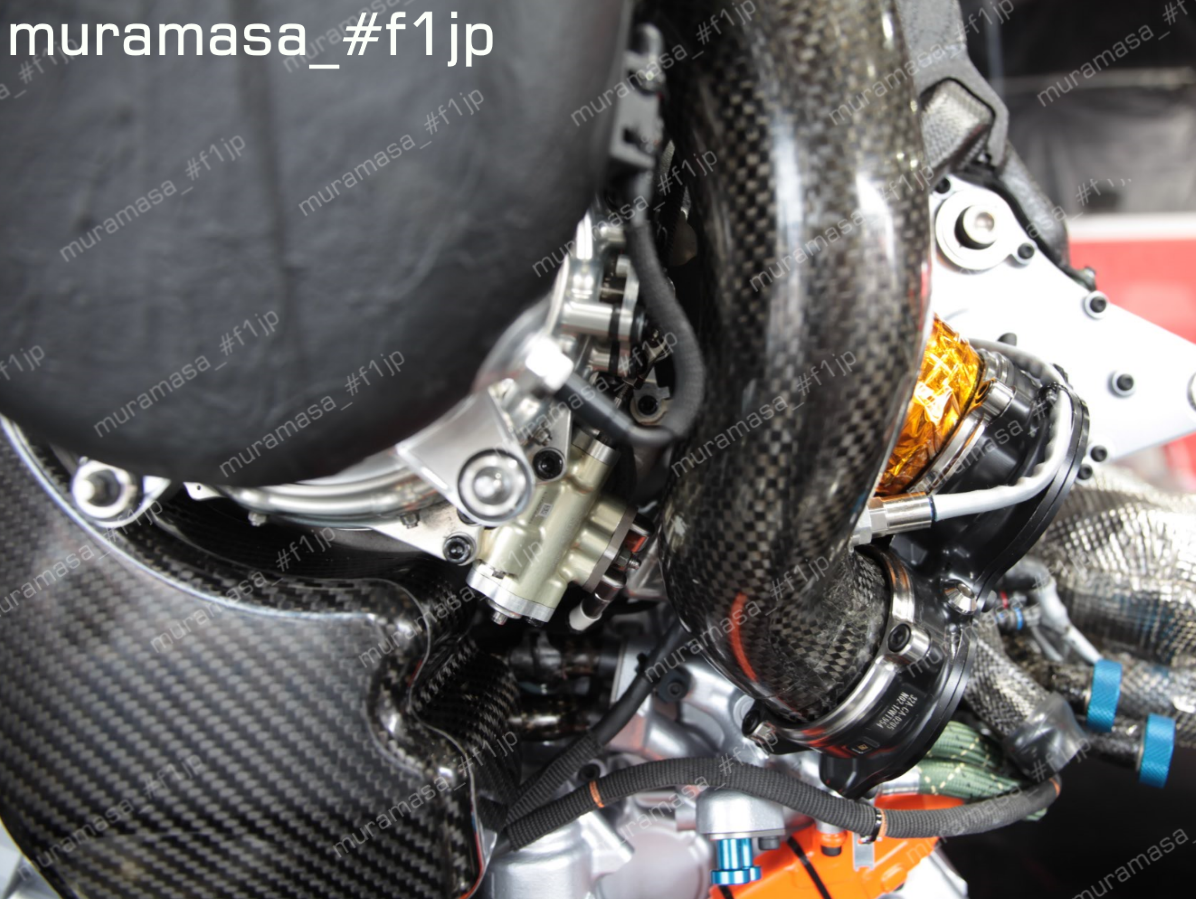
plenum chamber:
RA616H: 1 common chamber for both banks
RA617H: separate/independent chamber for each bank
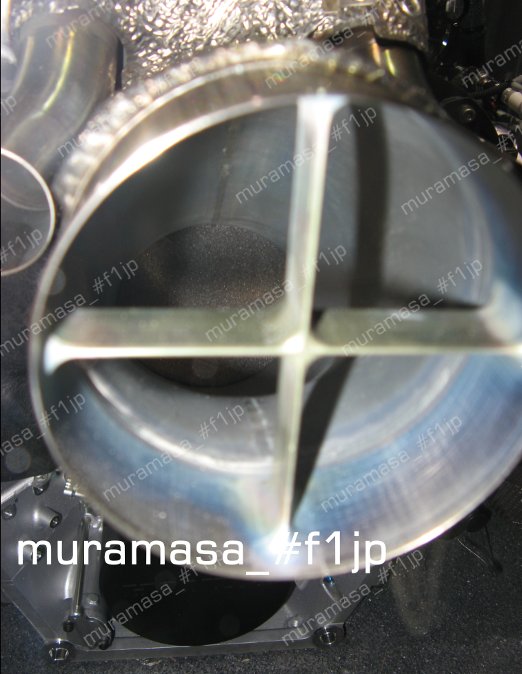
"Compressor, turbine and MGU-H were all located inside V, so it was difficult task to arrange Variable Induction System with 2015 and 2016 units. VIS has been positioned as X config (when viewed from front) with 3 cylinders of each bank opposed each other, but now only MGU-H is inside V with the 2017 unit, so we are able to arrange all the VIS funnels facing frontal direction. It's extremely simple config, so we can say that we have an ideal package regarding the 2017 inlet system. That's major difference from 2016. Also lowered the cog by that."
- VIS mechanism simplified and the length of stroke increased
- as a result, it's optimized for wider range of rpm
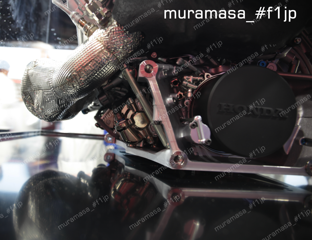
- On the other hand, oil tank has been severly compromised by the compressor being moved out of V
"Oil tank design was insufficient, so as a consequence, oil gets sucked through intake duct, together with blow-by gas. Once inhaled by intake, what's there next is compressor. Then oil enters into MGU-H from compresor, ending up damaging its bearing as a result."
(Not all the MGU-H failures was down to this cause)
"We made countermeasures one by one, like toughening bearing, cooling it more, making structure such that the oil does not enter in the first place, and so on. No doubt there are still more that can be done, so that's the subject to clear for 2018."
- Space allowed for engine is set by the regulation, so you cannot just make oil tank shape and size the way you want freely. Cannot make extra space to compensate the lost space by the protruding compressor. So what gets compromised is the oil tank
"It's not the issue about tank volume, but shape"
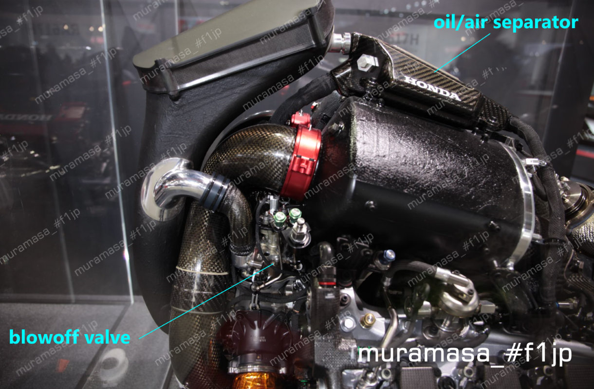
"Channel blow-by gas here (to the sub tank above plenum chamber). It has some degree of swirl structure/function inside. The key is how well you separate oil from air and let scavenge pump suck oil only."
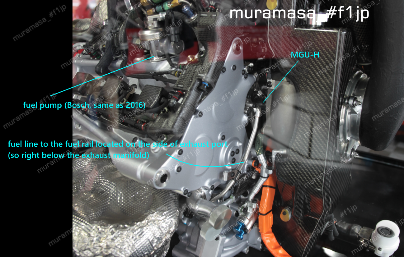
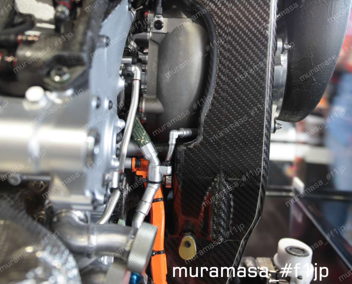
Fuel pump is positioned on cylinder head cover, same as RA616H. But the fuel line, which was placed along the ignition coils for RA616H, cannot be seen at the same location with RA617H. Therefore RA617H is not top injection.
RA615H: side injection on inlet port side.
RA616H: top injection
RA617H: The author is speculating that it's side injection on exhaust port side (can be seen in pics anyways)
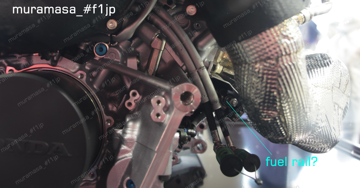
"We've trialed various positions for the injector, and we've adopted the layout that can be considered the best solution at this moment."
Gain of compression ratio between units
RA615H -> RA617H: 2+
R616H early specs -> RA617 final spec: 1+
"How you increase homogeneity of mixed air in the main chamber while maintaining enough A/F ratio in the sub chamber is the key. Managing air flow movement and the injected mist, and balancing its A/F and gas homogeneity in sub chamber is challenging."
"Generally, injector of direct injection engines of production cars is placed on the intake port side. This is a concept to mix fuel by the flow of air. RA616H's injectors are center-positioned, which was for the purpose of increasing air homogeneity and achieving superior combustion. However, there is spark plug at the center of chamber, so in terms of packaging it was quite tough. Therefore, we reviewed the injector position for RA617H."
"It was a start from minus / below zero. "
"Of course we foresaw what must be ahead, but we had to face more realistic outcomes as soon as we made it to V6 package. It is true that at the point of the season-opening race we were not able to reach the output level of the previous engine. We finally surpassed previous year's performance with the first update introduced early in the season. We exceeded/gained much further with the final spec too. It's not like you put sub-chamber and can get power instantly, it's not that simple. Size of tumble, angle of injection, size and angle of the hole, and so on, are the elements, then there is compression ratio to consider too. Appropriate tuning is essential in order to be able to use it nicely, so you proceed the development so as to obtain the most appropriate combustion."
"We've trialed dozens of different configurations for the sub chamber, and much more than that for the injector. If you consider increasing combustion efficiency and thermal efficiency under the current reg, pre-chamber is the path you must take. Current regulation will continue until 2020. We are going to continue development of increasing combustion speed, which includes increasing compression ratio, beyond 2018."
POP OFF VALVE
first version: channel air from the duct right after compressor directly
second version: channel the cooled air that went through intercooler
"(pop off valve config is) decided by taking both performance and packaging into consideration, but each config has its pros and cons"
WASTE GATE
RA615H/RA616H: 2 valves
RA617H: 1 valve
MGU-K: "one of the areas that went through significant change from 2016"
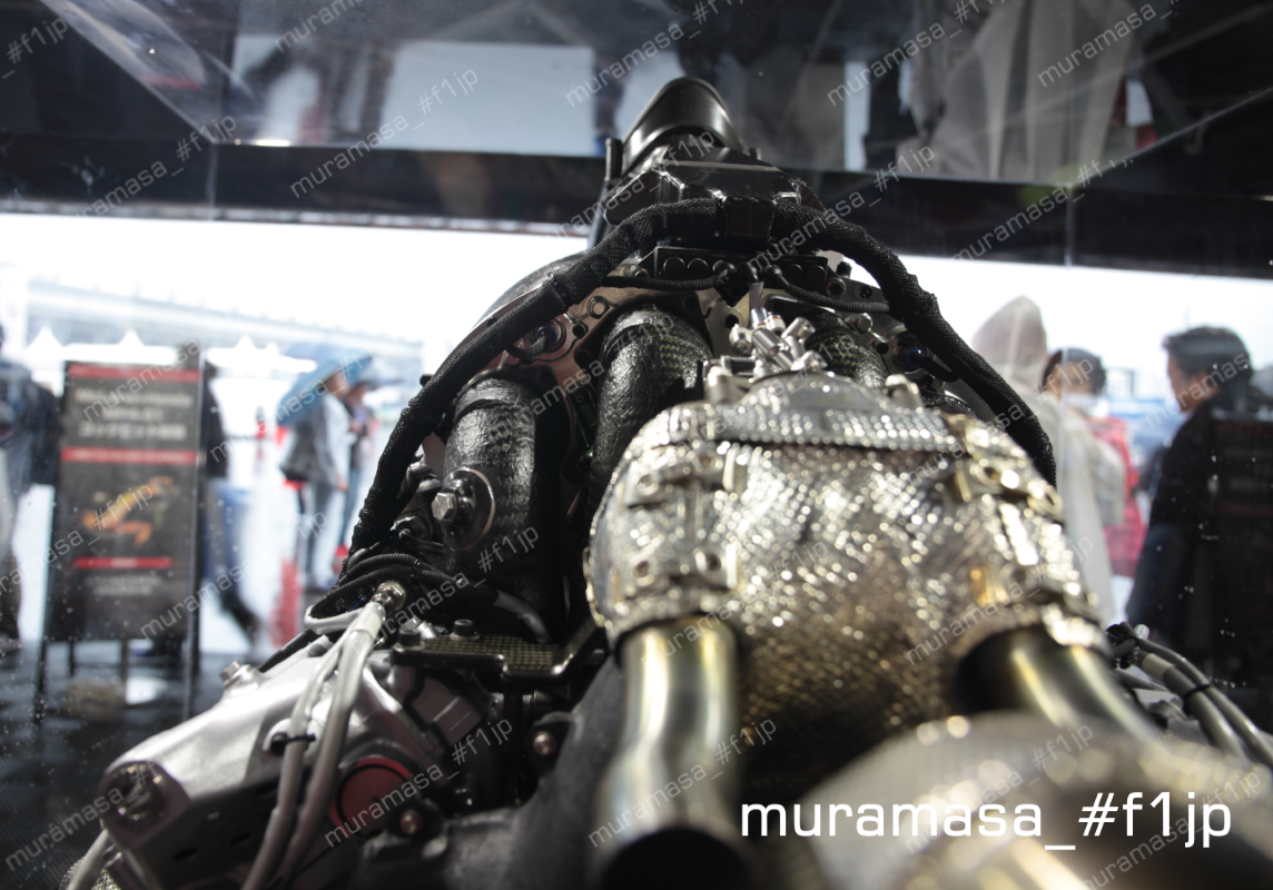
EXHAUST MANIFOLD:
RA615H: wrapped all pipes in bag
RA616H: wrapped each pipes individually
"waste less energy for RA616H's exhaust config by that way"
RA617: bag config
manifolds got closer to each other so "lose less energy because overall surface area becomes smaller that way"
---------------------------------------------
Engineers interviewed: Nakata and Fukao
"(On how the 2017 wider car affected the PU usage) certainly those inherent power tracks have become tougher, but what's more significant is that, tracks that used to be medium load previously have become considerably tougher. The increased speed/load due to wider and faster car affected the reliability more than the increased mileage per unit did. We evaluated reliability by calculating on simulation."
[ Telemetry Data Comparison between 2016 and 2017 for Spanish GP Quali ]
Barcelona T3
2016: half throttle in the middle for quite a while, lifting throttle completely for an instant
2017: full throttle almost entirely
Barcelona T9
2016: lift throttle completely
2016: lift throttle just a bit
"Cornering speed has increased. And generally the timing of opening pedal has got earlier and the timing of deceleration has got later, waiting until the last possible moment before pressing on brake. "
As a result, MGU-K regeneration amount has decreased
"We use the control method called e-boost, ie about letting exhast escape from waste gate to reduce exhaust pressure and extract maximum output from engine, while MGU-H is working as motor to obtain boost pressure"
"in 2016, MGU-H was making e-boost almost fully but in 2017 it's generating energy quite often here and there, enable to make e-boost"
Straight after T3
2016: MGU-H is making full e-boost
2017: full regeneration
So in 2017 T3 speed is faster but lacks top speed.
"(MGU-K deployment's) contribution to the lap time is big, so the concept of deploying MGU-K as much as possible is unchanged. In 2016, there was abundant energy even if MGU-K assist is (fully) used, so we were able to make e-boost of MGU-H. But this year it's short of energy, so no choice but to stop using e-boost."
MGU-K -> ES: 2MJ/lap
ES -> MGU-K: 4MJ/lap
MGU-H <-> ES: Unlimited
"What's called "extra harvest" is about taking advantage of unlimited exchange of energy between MGU-H and ES"
MGU-K -> MGU-H -> ES instead of MGU-K -> ES
"it's only 2MJ/lap with MGU-K -> ES, but with MGU-K->MGU-H->ES, you have extra few MJ added on top of the original 2MJ"
[Spa Quali telemetry comparison between 2016 and 2017]
"Belgium is a circuit where there was shortate of energy for deployment, so even in 2016 we were not able to use e-boost. "
- In 2017 MGU-K deployment starts at earlier point than 2016, so deployment runs out in the middle of T10 and T12.
- In 2016, driver was lifting throttle a bit in T15 but in 2017 it's full throttle.
- At the full throttle section from Eau Rouge to Kemmel, they are able to make full deployment throughout the section in both 2016 and 17.
MGU-K recovery is done not only at braking but also during acceleration. During the acceleration phase, turn ICE more than driver's pedal input and use the excess power of ICE to turn MGU-K for harvest. Called Partial Harvest at Honda.
[Telemetry comparison between Extra Harvest on and off]
Under braking (where MGU-K graph goes to the bottom = harvesting), MGU-H graph goes up and down repeatedly and rapidly, so graph looks like its area filled almost entirely during the phase or quake tremor graph.
"The idea itself (of Extra Harvest) already existed at the point of 2016, but there was MGU-H durability to consider, so we were contemplating when to introduce it by assessing the durability/performance balance. We trialed it at Belgium GP 2017, before fully introducing it from Italy onward."
- During Extra Harvest, MGU-H is busy switching between harvest and deployment back and forth rapidly in 20~40Hz range.
"During the acceleration phase, normally MGU-H makes a bit of deployment in order to keep boost pressure, but when conducting Extra Harvest, you use MGU-H by switching on and off. The reason is that you regenerate the amount of "On" (by using energy generated by MGU-K). You deploy MGU-H and give it inertia energy, then recover it at once."
"MGU-H handles not only the exchange of energy but also controls boost pressure. As a matter of course, we make Extra Harvest in a way that boost control is not affected."
- As a result of Extra Harvest, no more running out of deployment
"This 2MJ and 4MJ setting for MGU-K is well thought of in order to prompt elaboration of its use, also it's fine regulation in terms of encouraging makers to focus on MGU-H in development."
"In production cars, manufacturers have the type of hybrid system that assist the drive directly, but not the type that makes heat regeneration. Therefore FIA opened and left that particular area so that makers can focus on its development, I reckon."
"(What if full throttle period increase even further in 2018?) It's about balance between ICE power and MGU-H recovery. We must get that right."