- Login or Register
No account yet? Sign up

Honda F1 project leader Yusuke Hasegawa has outlined a number of reasons why Honda has been struggling so badly in the beginning of the 2017 Formula One season. He confirmed that lots of problems were not discovered while running on the dynamo meter.
1-4-3-6-2-5 Wazari, it's 1-4-3-6-2-5Wazari wrote:1-4-5-6-3-2? 1-5-3-6-2-4? 1-4-3-6-2-5? 1-4-2-5-3-6? or 1-2-3-4-5-6?

That I suppose is the trial and error part, especially if you're doing something novel with the crank, say treating it as a v4 and a v2. Of course no one knows, and we can only guess. First firing order is very interesting, 1-5-4-2-6-3, probably not possible?Wazari wrote:1-4-5-6-3-2? 1-5-3-6-2-4? 1-4-3-6-2-5? 1-4-2-5-3-6? or 1-2-3-4-5-6?
This is a clue isn't it? Does Honda number their V's per bank or along the crank?Wazari wrote:1-4-5-6-3-2? 1-5-3-6-2-4? 1-4-3-6-2-5? 1-4-2-5-3-6? or 1-2-3-4-5-6?
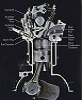
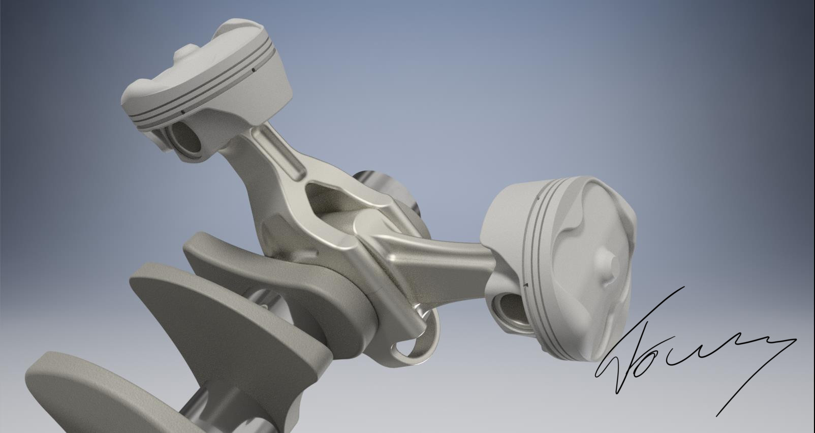
Interesting to note one of the reasons for layered bearings. The resulting increase in diameter around the journal provides more bearing surface area without making the blade wider.
I think it's standard on all blocks since they have to turn clockwise, right bank looking from the front = 123, left bank 456.roon wrote:This is a clue isn't it? Does Honda number their V's per bank or along the crank?Wazari wrote:1-4-5-6-3-2? 1-5-3-6-2-4? 1-4-3-6-2-5? 1-4-2-5-3-6? or 1-2-3-4-5-6?
I have a feeling Honda have designed a monster. Renault ought be careful with their taunts. This could be the sound of their defeat.Thunders wrote:So after hearing that Clip 3 Times on 3 different devices (at first i thought my Headphones died ^^) my first reaction were the exact words as the Renault answer to that Video: (yes i realise it's because they posted their fire up Video too, but the comment was fitting)
https://twitter.com/RenaultSportF1/stat ... 4726253572
No it's not different..godlameroso wrote: I think it's standard on all blocks since they have to turn clockwise, right bank looking from the front = 123, left bank 456.
Maybe it's different though.
I don't see any rules that would prevent the system used by Allison - bearing shell width same as overall width of fork rod, with bearing material on the outside of the centre of the shell for the blade rod to run.roon wrote:Interesting to note one of the reasons for layered bearings. The resulting increase in diameter around the journal provides more bearing surface area without making the blade wider.
In F1, the regs intend for the crank & rods to be monolithic. So they'd have to machine a diametrically larger step in the center of the journal to achieve a similar effect.

Well to be fair their comment wasn't about the Honda engine sound but because they posted their own Soundclip almost at te exact same time. So that was the awkward part.roon wrote:I have a feeling Honda have designed a monster. Renault ought be careful with their taunts. This could be the sound of their defeat.Thunders wrote:So after hearing that Clip 3 Times on 3 different devices (at first i thought my Headphones died ^^) my first reaction were the exact words as the Renault answer to that Video: (yes i realise it's because they posted their fire up Video too, but the comment was fitting)
https://twitter.com/RenaultSportF1/stat ... 4726253572
#aerogollumturbof1 wrote: YOU SHALL NOT......STALLLLL!!!
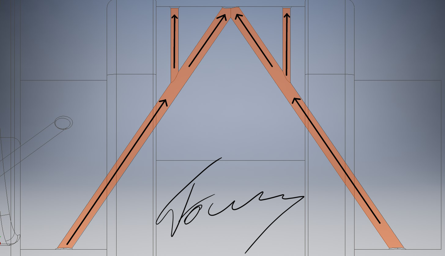
Good idea, in combination with the bearing system someone has shown above, that could really worktok-tokkie wrote:On the forked con-rod. Could two narrow rods be used in place of the forked rod? It means different pistons for the single & twin rod cylinders. But is there room in the piston for the small ends of the twin rod cylinders? Then two straight rods so the twisting issue falls away.