2014-2020 Formula One 1.6l V6 turbo engine formula

All that has to do with the power train, gearbox, clutch, fuels and lubricants, etc. Generally the mechanical side of Formula One.
User avatar
Redstorm
0
Joined: 24 Feb 2010, 12:07

Re: Formula One 1.6l turbo engine formula as of 2013

Post

I like the thought but would that not be then interpretted as a movable aero device?

gridwalker
gridwalker
7
Joined: 27 Mar 2009, 12:22
Location: Sheffield, UK

Re: Formula One 1.6l turbo engine formula as of 2013

Post

The EBD wasn't viewed as moving, despite the engine containing A LOT of moving parts.

Where do you draw the line?
"Change is inevitable, except from a vending machine ..."

User avatar
flynfrog
Moderator
Joined: 23 Mar 2006, 22:31

Re: Formula One 1.6l turbo engine formula as of 2013

Post

Tok- Re read your post makes more sense now but having a shaft that long spinning at those speeds is not a great idea. you will also have to have more bearings to support it. You are also adding mass not a good thing. much easier to move the intake pipe.

Marcush- Indy cars are NA and have been for quite a while.

Auto- your response times are you electric system would be terrible no where near the quick spooling turbo it once was. Not to mention the weight of the components and the losses involved

autogyro
autogyro
53
Joined: 04 Oct 2009, 15:03

Re: Formula One 1.6l turbo engine formula as of 2013

Post

Response times would not be a problem if the KERS energy is fed to the compressor on braking and through corners. The induction wastegate would be open allowing the engine revs to drop but using the high rpm of the compressor to suck air from a low pressure DF source and blowing a slot?.
The compressor would already be at speed for launch down the strait when wastegate closes applying pressure to induction.
Using KERS this way reduces or does away with the need for KERS storage as well.

User avatar
WhiteBlue
92
Joined: 14 Apr 2008, 20:58
Location: WhiteBlue Country

Re: Formula One 1.6l turbo engine formula as of 2013

Post

The system that is likely to work with best efficiency would be a combination of an oversized exhaust gas turbine with a conventionally dimensioned charging compressor on one shaft. In addition the shaft would need to be connected to a power source/sink. During engine spool up the power source would kick in accelerating the compressor beyond the means of the turbine to build the compressor power without turbo lag. When the engine builds rpm and the turbine reaches the change over point and starts to deliver more power than the compressor needs the external power flow reverses. Power is now taken from the turbo shaft to prevent the compressor to over pressurize. Such a system does away with the need for a waste gate and anti lag engine mapping. It is capable of delivering additional compounded power in the order of 10-15% of the engine power. It is feasible for F1 because the engines run mostly on full throttle compared with road cars.

We have already discussed two relatively simple methods to achieve the reversing of the external power flow. Hybrid cars with electric high energy storage can use an electric servo MGU which is fast enough and only adds a few kg for the MGU and the inverter. With compound power of 40-60 kw the power/weight ratio is attractive. The battery capacity is available already.

If the car has no hybrid drive train you can achieve the same thing with a Torotrak CVT. It is equally capable of reversing the power flow from the engine crank shaft to the turbo shaft. The weight and efficiency quoted by Torotrak for such designs look quite feasible.

Putting the ICE and the turbo machines on the same shaft makes no sense IMO. The turbo shaft could be on one side of the engine as BMW did or it could be above the gear box or diff. I proposed that config already in the old thread and did a 2D power point graphic on it. The 3D design by ringo just makes it a bit easier to understand.
Formula One's fundamental ethos is about success coming to those with the most ingenious engineering and best .............................. organization, not to those with the biggest budget. (Dave Richards)

autogyro
autogyro
53
Joined: 04 Oct 2009, 15:03

Re: Formula One 1.6l turbo engine formula as of 2013

Post

I have never suggested connecting the turbo shaft to the ICE.
In my idea the compressor will always be at max rpm so there is never any lag or the inefficiency of spooling up.

chepoi
chepoi
0
Joined: 14 Jan 2004, 11:35
Location: Kuala Lumpur, Malaysia

Re: Formula One 1.6l turbo engine formula as of 2013

Post

2023 800cc engine? turbo? DDD? KERS? no refueling, no tyre changing? lol!!!!

User avatar
PlatinumZealot
551
Joined: 12 Jun 2008, 03:45

Re: Formula One 1.6l turbo engine formula as of 2013

Post

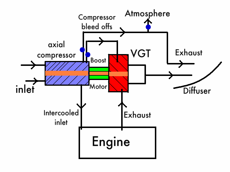
WhiteBlue wrote:The system that is likely to work with best efficiency would be a combination of an oversized exhaust gas turbine with a conventionally dimensioned charging compressor on one shaft. In addition the shaft would need to be connected to a power source/sink. During engine spool up the power source would kick in accelerating the compressor beyond the means of the turbine to build the compressor power without turbo lag. When the engine builds rpm and the turbine reaches the change over point and starts to deliver more power than the compressor needs the external power flow reverses. Power is now taken from the turbo shaft to prevent the compressor to over pressurize. Such a system does away with the need for a waste gate and anti lag engine mapping. It is capable of delivering additional compounded power in the order of 10-15% of the engine power. It is feasible for F1 because the engines run mostly on full throttle compared with road cars.

We have already discussed two relatively simple methods to achieve the reversing of the external power flow. Hybrid cars with electric high energy storage can use an electric servo MGU which is fast enough and only adds a few kg for the MGU and the inverter. With compound power of 40-60 kw the power/weight ratio is attractive. The battery capacity is available already.

If the car has no hybrid drive train you can achieve the same thing with a Torotrak CVT. It is equally capable of reversing the power flow from the engine crank shaft to the turbo shaft. The weight and efficiency quoted by Torotrak for such designs look quite feasible.

Putting the ICE and the turbo machines on the same shaft makes no sense IMO. The turbo shaft could be on one side of the engine as BMW did or it could be above the gear box or diff. I proposed that config already in the old thread and did a 2D power point graphic on it. The 3D design by ringo just makes it a bit easier to understand.

You are suggesting putting a motor/generator around the power shaft in between the turbine and compressor? This is actually a good Idea. I think it's being used already so that is definitely a possibility for 2013.

Electronically controlled anti lag is a good idea.

For auto-gyros Idea. If you want a have a compressor spining at one speed, and have the provisions to do it, then a axial compressor will be the best choice. High efficiencies but Extremely high pressure ratios though, and the stability range is very small. So you need to have that electronic motor pumping in energy through the turns and even a variable vane Turbine to keep the speed of the axial compressor up.
Then again Since the pressure ratio is so high, you can run the axial compressor at half capacity by just bleeding off excess boost back into the turbine, or over the diffuser. If this is electronically controlled you can keep a relatively constant boost level.
🖐️✌️☝️👀👌✍️🐎🏆🙏

User avatar
PlatinumZealot
551
Joined: 12 Jun 2008, 03:45

Re: Formula One 1.6l turbo engine formula as of 2013

Post

This what I mean. You can see the Variable geometry turbine. The axial copressor. the Boost motor/generator and the two bleed offs. One to boost back into the turbine (lower egts as well), and one to add more blow the diffuser (if necessary) or even blow the wings.

Image
🖐️✌️☝️👀👌✍️🐎🏆🙏

User avatar
747heavy
24
Joined: 06 Jul 2010, 21:45

Re: Formula One 1.6l turbo engine formula as of 2013

Post

I guess Marcus had perhaps something like this in mind:

Image
Image
"Make the suspension adjustable and they will adjust it wrong ......
look what they can do to a carburetor in just a few moments of stupidity with a screwdriver."
- Colin Chapman

“Simplicity is the ultimate sophistication.” - Leonardo da Vinci

marcush.
marcush.
159
Joined: 09 Mar 2004, 16:55

Re: Formula One 1.6l turbo engine formula as of 2013

Post

747heavy wrote:I guess Marcus had perhaps something like this in mind:
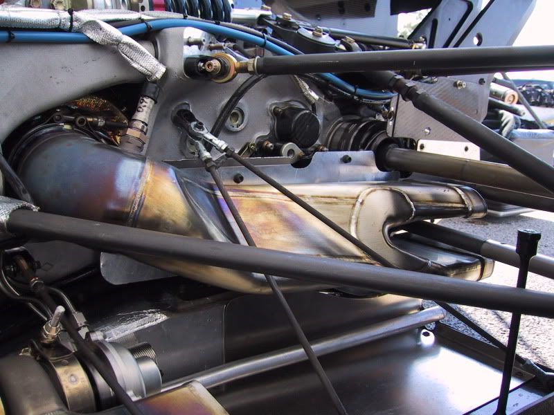
absolutely..you easily beat me retrieving the perfect pictures..and that seems to be one of your minor assets.. =D>

autogyro
autogyro
53
Joined: 04 Oct 2009, 15:03

Re: Formula One 1.6l turbo engine formula as of 2013

Post

OK put a sprag (one way clutch) beetween the turbine and compressor at the turbine end, to allow the compressor to rev above the turbine rpm electricaly and it can then be kept at max revs but driven directly by the turbine, when exhaust boost is available.

User avatar
ringo
227
Joined: 29 Mar 2009, 10:57

Re: Formula One 1.6l turbo engine formula as of 2013

Post

747heavy wrote:I guess Marcus had perhaps something like this in mind:

Image
Image
what car is this? =D>
That's what i am talking about! It add some length to the car, but i guess with only 1 bank of headers, it should be better in terms of piping.
Now imagine how narrow a 4 cylinder F1 car would be with this layout and the renault r30 angled radiator setup.
For Sure!!

marcush.
marcush.
159
Joined: 09 Mar 2004, 16:55

Re: Formula One 1.6l turbo engine formula as of 2013

Post

the Galmer G92 used a setup like this to win in Indy .I´m not quite sure if it is this car .
As this used a Chevy engine and we see a Cosworth below ...this hints at others using similar packaging .

User avatar
ringo
227
Joined: 29 Mar 2009, 10:57

Re: Formula One 1.6l turbo engine formula as of 2013

Post

The compressor drive motor idea's a pretty good one, but it requires electrical energy, for such a small rev range, with maybe a difference of milli seconds in boost response difference. I think it would be better to have the simple turbine compressor relationship.
The motor inbetween them, i would just use that to generate power to power the wheels.
Putting the power back into the compressor makes sense off boost, but it will still take considerable power to spool the compressor unless the compressor is in a vacuum. If the compressor is in a vacuum so it can speed up with minimal power, then no boost for the engine since no compressed air is flowing.
So it's back at square 1, the turbine is the best accelerator for the loaded compressor.
If the motor can't accelerate the loaded compressor faster than the turbine it makes no sense. It has to be able to do that for it to be viable.
If it can assist the turbine, instead of work independently, then all the better.
For Sure!!