2012 Exhaust Blowing & Coanda

Here are our CFD links and discussions about aerodynamics, suspension, driver safety and tyres. Please stick to F1 on this forum.
Post Reply
hardingfv32
32
Joined: 03 Apr 2011, 19:42

Re: 2012 Exhaust Blowing

Post

In this illustration with a pressure scale:

1) Why is the pressure so low at the exhaust outlet?

2) Why is the pressure lowest at the curved floor of the channel? Is this a how a Coanda Effect presents itself?

3) Why does the pressure increase after the flow clears the channel? The exterior flow is being added to the exhaust flow?

Image

Brian

User avatar
Rideway
0
Joined: 12 Sep 2009, 13:31
Location: UK

Re: 2012 Exhaust Blowing

Post

hardingfv32 wrote:In this illustration, using the scale provided the exhaust flow leaves the pipe at around 100 m/s while it was specified that the exhaust flow used was 348 m/s. What is the reason for this?
Scale is up to 100m/s. So everything faster than that, will be red.
hardingfv32 wrote:In this illustration with a pressure scale:

1) Why is the pressure so low at the exhaust outlet?

2) Why is the pressure lowest at the curved floor of the channel? Is this a how a Coanda Effect presents itself?

3) Why does the pressure increase after the flow clears the channel? The exterior flow is being added to the exhaust flow?
1. High speed fluid. So according to Bernouilli, pressure must be low.
2. I think it is 100% because of Coanda effect. The change in the momentum of the air flow is reacted in a reduced pressure (Coanda effect) which attach and acceleretes the air flow.
3. I think you are right there.

In any case i think that the picture could change considerably if the tires were rotating.

Cheers

User avatar
ringo
227
Joined: 29 Mar 2009, 10:57

Re: 2012 Exhaust Blowing

Post

ringo wrote:
shelly wrote:
no it wont. :) There are some examples showing air coming from the sides with tunneled floors, but the F1 floor is different.

After the throat there is no inward tendency for air flow.
What you will find also is that the upwash from the brake duct airfoils will influence the exhaust to go upward as well.

But to get back to mclaren, i think this is a nice concpept but it's not as effective as redbull's. I have not seen the downforce numbers, but there are a few things i will point out as to why this is just a gimmick soley designed to show the FIA that they can bend the rules.
I dont think it's very dependable, similar to the front exhuast on the renault.

Mclaren will copy redbull by race 6. :lol:
Just quoting myself to pickup from where i left off.

This solution is probably not as effective as redbull's becuase of the increased number dependencies for it to operate optimally.
Hope that is understandable.

It's ability to create downforce depends on these things:

Engine speed,
air speed,
coanda trough shape.

So if we look at the full range of these factors you will see there is probably a certain engine speed and car speed where the exhuast will flow as intended. Other times it will not flow as intended.
The fact that the coanda trough is fixed for the whole race weekend, unlike the other factors, it can only operate as intended with a certain engine speed and road speed range.
This is the same conundrum Renault put them self in last year with the R31. There is fixed body geometry that only works with specific conditions. And they had the low speed downforce problems, which were unsolvable.

In contrast redbull have this variable:

engine speed.

Reason being the exhuasts shoot straight, there is no depency on air speed since the air is already pointed where it is intended to blow. Air speed wont chage its direction. Body geomety is fixed but this is not an issue as there is no need to influence the flow with the bodywork and no need to fine tune.

Basically Redbull will have maximum downforce all the live long day at any part of the track. Mclaren cannot have this as their ssytem is tuned; ie fixed for a sweet spot.
You even see the body panel screws for the coanda pipe showing these guys have probably dozens of them slapping on trying to find a balance for each track.

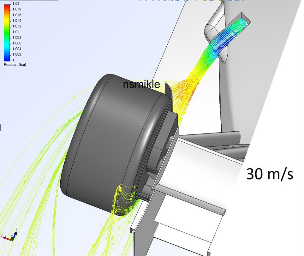
Therefore i predict a switch to the redbull design. We see from the CFD that after the air bends to the floor, there is a great loss in speed and energy. By the time it's at the diffuser you can say the relative speed to free stream is marginal.
This is why i believe Mclaren were more focused on showing up the FIA saying "we have a savvy set of engineers we can still blow the diffuser!" and not actually trying another route looking at other areas to blow.
Too fixated on the diffuser, while redbull have other things in mind that reap more consistent and staying performance.
For Sure!!

hardingfv32
32
Joined: 03 Apr 2011, 19:42

Re: 2012 Exhaust Blowing

Post

Rideway wrote:[Scale is up to 100m/s. So everything faster than that, will be red.
So then the exhaust flow goes from 348 to 60 m/s in about 200 mm? Then 60 to 40 m/s in the next 800 mm or so. Does this sound correct for a slowing air flow? Very non-linear?

Does the flow being illustrated include the air flow around the body mixed with the exhaust flow or can it be just the exhaust flow?

Do you have an 'exhaust off' condition?

I am wondering how fast the exhaust flow goes ambient.

Brian

User avatar
ringo
227
Joined: 29 Mar 2009, 10:57

Re: 2012 Exhaust Blowing

Post

it doesn't include the body flow. It's just showing that of the pipe.
For Sure!!

hardingfv32
32
Joined: 03 Apr 2011, 19:42

Re: 2012 Exhaust Blowing

Post

ringo wrote:it doesn't include the body flow. It's just showing that of the pipe.
But it is being acted upon by body air flow off screen? This is a common option with the programs?

Brian

User avatar
Rideway
0
Joined: 12 Sep 2009, 13:31
Location: UK

Re: 2012 Exhaust Blowing

Post

He simulated the air flow at different speeds so yes. With most CFD programs you can plot particle flow starting fron almost anywhere: inlet (most common), a reference plane or in this case from
exhaust exit. But im sure he simulated the whole air flow, if not it wouldnt make sense to simulate different speeds.

lombers
0
Joined: 05 Feb 2012, 13:40

Re: 2012 Exhaust Blowing

Post

I'm no engineer but I too have some questions about the CFD.

What is the speed of the exhaust gasses leaving the exhaust pipe? Obviously this would be throttle sensitive, but I would expect to see more influence on the air flow from the exhausts, specifically at full throttle. I am also curious on how throttle position affects this flow and what if any negative effects it might have on a setup such as this.

Regardless it does look like a fantastic solution if it indeed works this way...

hardingfv32
32
Joined: 03 Apr 2011, 19:42

Re: 2012 Exhaust Blowing

Post

The exhaust temp at the outlet is stated at 850 C for this simulation. I think 850 C should be the temp at the exhaust port, not the end of the exhaust system. I have a study on a NASCAR system that states 850 C at the port and 150 C at the end of the exhaust system. The NASCAR system is no more than 25% longer.

So the exhaust temps used is this simulation are too high. What is the effect?

Is the heat in the exhaust flow a net benefit? At a minimum hot air is not as dense as cool ambient air.

Brian

User avatar
PlatinumZealot
551
Joined: 12 Jun 2008, 03:45

Re: 2012 Exhaust Blowing

Post

hardingfv32 wrote:In this illustration, using the scale provided the exhaust flow leaves the pipe at around 100 m/s while it was specified that the exhaust flow used was 348 m/s. What is the reason for this?


Brian
Remember I said I limited the colour scale to 100m/s so a good range of colours can be seen. The speed coming out of the exhaust pipe is 348 m/s. I didn't want to extend the colour scale to 348 m/s because everyithing woould be only red and blue.
๐Ÿ–๏ธโœŒ๏ธโ˜๏ธ๐Ÿ‘€๐Ÿ‘Œโœ๏ธ๐ŸŽ๐Ÿ†๐Ÿ™

User avatar
PlatinumZealot
551
Joined: 12 Jun 2008, 03:45

Re: 2012 Exhaust Blowing

Post

Rideway wrote:
hardingfv32 wrote:In this illustration, using the scale provided the exhaust flow leaves the pipe at around 100 m/s while it was specified that the exhaust flow used was 348 m/s. What is the reason for this?
Scale is up to 100m/s. So everything faster than that, will be red.
hardingfv32 wrote:In this illustration with a pressure scale:

1) Why is the pressure so low at the exhaust outlet?

2) Why is the pressure lowest at the curved floor of the channel? Is this a how a Coanda Effect presents itself?

3) Why does the pressure increase after the flow clears the channel? The exterior flow is being added to the exhaust flow?
1. High speed fluid. So according to Bernouilli, pressure must be low.
2. I think it is 100% because of Coanda effect. The change in the momentum of the air flow is reacted in a reduced pressure (Coanda effect) which attach and acceleretes the air flow.
3. I think you are right there.

In any case i think that the picture could change considerably if the tires were rotating.

Cheers
The tyres are rotating - you can see the effect of the rotating tyre as it pulls the air around.
๐Ÿ–๏ธโœŒ๏ธโ˜๏ธ๐Ÿ‘€๐Ÿ‘Œโœ๏ธ๐ŸŽ๐Ÿ†๐Ÿ™

User avatar
PlatinumZealot
551
Joined: 12 Jun 2008, 03:45

Re: 2012 Exhaust Blowing

Post

hardingfv32 wrote:In this illustration with a pressure scale:

1) Why is the pressure so low at the exhaust outlet?

2) Why is the pressure lowest at the curved floor of the channel? Is this a how a Coanda Effect presents itself?

3) Why does the pressure increase after the flow clears the channel? The exterior flow is being added to the exhaust flow?

Brian
1. it's only because it comes out into the environment. The static pressure will be slightly higher than the ambient.

2. I think it's only because the fluid is accelerating around the bend.

3. The total pressure comes into play as the exhausts hits the flow and slows down. There is also a high pressure bubble around the front of the tyres slowing down everything near that area.
๐Ÿ–๏ธโœŒ๏ธโ˜๏ธ๐Ÿ‘€๐Ÿ‘Œโœ๏ธ๐ŸŽ๐Ÿ†๐Ÿ™

User avatar
Rideway
0
Joined: 12 Sep 2009, 13:31
Location: UK

Re: 2012 Exhaust Blowing

Post

n smikle wrote:The tyres are rotating - you can see the effect of the rotating tyre as it pulls the air around.
You are right, didnt apreciate it at first sight. Sorry.

By the way, can you please tell which solver did you use and why, if you performed mesh sensivity studies, convergence criteria etc? Im quite interested in the technical aspects of CFD simulation. Thanks a lot in advance.

And i am also interested in the exhaust velocity, as lombers pointed. Where did you get that figure from?
n smikle wrote:Exhaust speed out of the pipe at 225 liter/second and 850C is about 348 m/s.
Q=V*A so 225 l/s = 0.225 m^3/s = V*A = 348 m/s * A
so A=6,4656*e-4 m^2 which gives a radious of r=14,346mm which doesnt make sense to me. Regulations says at point 5.8.3 "Form a thinโ€walled unobstructed right circular cylinder whose internal diameter is no greater than 75mm [...]".

User avatar
PlatinumZealot
551
Joined: 12 Jun 2008, 03:45

Re: 2012 Exhaust Blowing

Post

Rideway wrote:
n smikle wrote:The tyres are rotating - you can see the effect of the rotating tyre as it pulls the air around.
You are right, didnt apreciate it at first sight. Sorry.

By the way, can you please tell which solver did you use and why, if you performed mesh sensivity studies, convergence criteria etc? Im quite interested in the technical aspects of CFD simulation. Thanks a lot in advance.

And i am also interested in the exhaust velocity, as lombers pointed. Where did you get that figure from?
n smikle wrote:Exhaust speed out of the pipe at 225 liter/second and 850C is about 348 m/s.
Q=V*A so 225 l/s = 0.225 m^3/s = V*A = 348 m/s * A
so A=6,4656*e-4 m^2 which gives a radious of r=14,346mm which doesnt make sense to me. Regulations says at point 5.8.3 "Form a thinโ€walled unobstructed right circular cylinder whose internal diameter is no greater than 75mm [...]".
I got the exhaust volume flow rate from the recent Williams F1 documentary. It was not far off my previous calculations though. I converted it to a mass flow rate because the density of it changes as it goes through the engine. Air flow is normally given at "Normal liters per secon" Nl/m or "Standard cupic feet per minute," SCFM which is the flow it would be at atmospheric pressure.

Air is compressible and it cannot travel faster than the speed of sound at whatever density it is at. So that is why your calculation will not correlate - especially at those speeds as it comes out of the pipe.

The velocity figure is a result from the calculation.

I have to look on the computer to tell you what solver is used. It must be the default Solid works solver. I am not educated in Computational Fluid Dynamics so you are asking the artist what chemicals make the paint 8) - I can only say how to paint.

Convergence criteria are typical. Like the mass flow into an exit, the pressure above a surface, a bulk average - if you wish, the max, the min - of any property you wish. Whatever properties you know will stabilise around the same time as the property or area of flow you are interested in.

So I decide which flows(or other effects) affects the flows in the loaction that I am interested in - and I decide which properties should stabilise to give me a satisfactory result . I then simply select the surfaces or even a single surface, from the "involved" areas and select which properties must converge/stabilise for the calculation to finish.

I actually setup this CFD study a long time ago to observe another exhaust behaviour. For this simulaiton I just reopened and modified the study - I have to open up the file again to see what convergence criteria I had.

This is a non-transient study so it is easier. I have done transient studies though where I set the time of calcuation and the number of iterations per step and the time step.

Mesh sensitivity studies - I only have done that a few times in the past and it was not worth doing into to show this. This is just a simple demonstration - the general behavior is all I wanted to observe. I was not doing this to get any numbers or study any fine flows. Luckily I did not have any overly long calculation times - about 15 minutes - I also checked the flows on higher mesh settings and the flow behavior stays the same. Overall I was satisfied with the default mesh settings so no need to fine tune the mesh.

I notice you guys are trying to "feel" me out on this CFD thing. :lol:
Last edited by PlatinumZealot on 01 Mar 2012, 21:34, edited 1 time in total.
๐Ÿ–๏ธโœŒ๏ธโ˜๏ธ๐Ÿ‘€๐Ÿ‘Œโœ๏ธ๐ŸŽ๐Ÿ†๐Ÿ™

hardingfv32
32
Joined: 03 Apr 2011, 19:42

Re: 2012 Exhaust Blowing

Post

n smikle wrote:Exhaust speed out of the pipe at 225 liter/second and 850C is about 348 m/s.
I am not sure how to relate to the above information, but this article, pg 44, puts the flow at the exhaust valve at 284 m/s for a 16-18K rpm for a MotoGp engine. I do not see how a F1 engine is going to be at 348 m/s at the exhaust tip. You lose about 25% flow every 90 deg bend I believe in a normal racing exhaust system. Typically about 270 degrees of bend in a F1 primary exhaust tube.

http://www.profblairandassociates.com/p ... basics.pdf

Brian
Last edited by hardingfv32 on 02 Mar 2012, 01:08, edited 1 time in total.

Post Reply