Adams car question

Here are our CFD links and discussions about aerodynamics, suspension, driver safety and tyres. Please stick to F1 on this forum.
Greg Locock
233
Joined: 30 Jun 2012, 00:48

Re: Adams car question

Post

Time, and lots of correlation data. The training course is OK if you want to build templates, and that is one thing they make a big deal about, but in reality a car company might need a new template once in 5 years, the nitty gritty of getting your models to (a) run and (b) give reasonably accurate results is mostly done by talking to other people.

You should probably grab a copy of Damian Harty's book, The Multibody Systems Approach to Vehicle Dynamics, as should I!

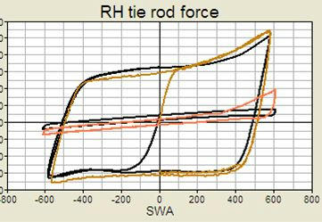
I'm pretty bad at the theoretical side of the Solver but when I'm given the time I can make it do what I need. Here's some nice curves showing parking efforts on concrete and on a greased plate. Black is ADAMS, orange and brown is test. The weird spike in the test data is due to bending in the tie rod we think.

https://www.mediafire.com/convkey/2247/ ... 0xu36g.jpg

Image

babias
0
Joined: 16 Apr 2018, 13:16

Re: Adams car question

Post

Thank you, now I 've found out the way to understand the outputs of Adams/Car. The other problem that I 've encountered is with static load simulations. Analyzing results I made the equilibrium of forces on each component of the suspension (control arms, pushrod, tierod) but there is an "error" on the vertical force on the upright. If I set a vertical force on the contact patch equal to 1500N I loose a part of this load between tire and spindle joint (around 60 N) and another part between spindle joint and control arms-tie rod joints (around 10 N). On X and Y directions the equilibrum is correct. Do you know why?

Greg Locock
233
Joined: 30 Jun 2012, 00:48

Re: Adams car question

Post

Your tire weighs 6 kg.

babias
0
Joined: 16 Apr 2018, 13:16

Re: Adams car question

Post

Greg Locock wrote:
06 Nov 2019, 14:19
Your tire weighs 6 kg.
Ops…I didn't consider the mass contribution on these equilibrium equations. Thank you very much!

browney
2
Joined: 15 Apr 2012, 10:13

Re: Adams car question

Post

With the race-orientated users around here. I was curious if anyone has determined the best method of altering ride height? You can do it with changing pre-load on springs (so the car 'pops up' so that the spring load = the sprung wight once the solve starts). You could also write a bunch of construction frame maths that moves the suspension around with parameters.

Was just curious if anyone does ride height sweeps and how they prefer to do it?

Greg Locock
233
Joined: 30 Jun 2012, 00:48

Re: Adams car question

Post

Invariably I change the free length of the spring. The other option would be to alter the location of the spring hardpoints. This would be a bad solution for a MacP, if your model has the fidelity to capture the effect of spring line of action eccentricity on the friction in the piston and top seal. We handle that in a different program, and in fact in the vehicles I work on it isn't an issue.

browney
2
Joined: 15 Apr 2012, 10:13

Re: Adams car question

Post

Yeah, preload or free length of the spring does it but it is a less elegant method than I have been looking for. Ideally they would incorporate the ability to move models using the joints like cad constraints in subsystems before solving (Ansys has this feature called 'configure joints').

browney
2
Joined: 15 Apr 2012, 10:13

Re: Adams car question

Post

What is regarded as the best software for vehicle simulation in a motorsport context?

It doesn't seem like ADAMS car was particularly designed with motorsport in mind?

VI-Grade sell a VI-motorsport package, however there are offerings from other providers such as car-maker and chassissim.

Is there one package that has taken a leading position?

Greg Locock
233
Joined: 30 Jun 2012, 00:48

Re: Adams car question

Post

That depends on what you want to simulate. I asked my supervisor why we used ADAMS when for 99% of the work at the time a bicycle model would do. His answer was (a) we are a component based company and switching components is easier than in a bicycle model, and (b) relating improved performance in a modified bicycle model back to components is not a 1:1 process.

In the case of motorsports I'd have thought your fundamental tradeoffs were best evaluated in a laptime simulator, and then it's a case of using less abstracted models to deliver the vehicle model you've optimised in the lapsim.

babias
0
Joined: 16 Apr 2018, 13:16

Re: Adams car question

Post

Hi, I have another question regarding Adams Car. I have found that there is a quite big difference between the wheel center rate and the wheel center rate evaluated multiplying the transmission ratio squared with the spring rate (that is linear). The transmission ratio is evaluated as the slope of the spring length variation with respect to the wheel travel and all the simulations are performed in parallel travel. Comparing the two results I have found that the two results are quite similar in rebound wheel travel but in the final part of the bump travel the wheel center rate given by adams decreases a lot while the "kinematic" increases.
Thank you in advance!

Greg Locock
233
Joined: 30 Jun 2012, 00:48

Re: Adams car question

Post

We call that the motion ratio. I don't ever see that, as we use jounce bumpers.

Plot spring length vs vertical wheel travel

Do you have bushings in your model, or flex parts?

User avatar
Tim.Wright
330
Joined: 13 Feb 2009, 06:29

Re: Adams car question

Post

babias wrote:
19 Jul 2021, 09:26
Hi, I have another question regarding Adams Car. I have found that there is a quite big difference between the wheel center rate and the wheel center rate evaluated multiplying the transmission ratio squared with the spring rate (that is linear). The transmission ratio is evaluated as the slope of the spring length variation with respect to the wheel travel and all the simulations are performed in parallel travel. Comparing the two results I have found that the two results are quite similar in rebound wheel travel but in the final part of the bump travel the wheel center rate given by adams decreases a lot while the "kinematic" increases.
Thank you in advance!
If you can upload the plot it will be much easier to understand. If you have a bumpstop in the model can cause a reduction in the motion ratio
due to it causing the link bushing to flex radially instead of predominantly rotationally.
Not the engineer at Force India

babias
0
Joined: 16 Apr 2018, 13:16

Re: Adams car question

Post

Greg Locock wrote:
19 Jul 2021, 10:54
We call that the motion ratio. I don't ever see that, as we use jounce bumpers.
Plot spring length vs vertical wheel travel
Do you have bushings in your model, or flex parts?
Tim.Wright wrote:
19 Jul 2021, 14:25
If you can upload the plot it will be much easier to understand. If you have a bumpstop in the model can cause a reduction in the motion ratio
due to it causing the link bushing to flex radially instead of predominantly rotationally.
I am using the fsae template and under "kinematic toggle" I selected kinematic. I have also deactivated the bumpstops by setting the curve always equal to zero.
Wheel rate:
Image
Spring length:
Image
The spring rate in the model is 240 N/mm and the motion ratio evaluated as the slope of the spring length plot increases from 0.52 to 0.66

User avatar
Tim.Wright
330
Joined: 13 Feb 2009, 06:29

Re: Adams car question

Post

Looks like the motion ratio is quite non-linear. Try using the complete formula for calulating the wheel rate which takes into account motion ratio non-linearities:
Kwheel = Kspring x MotionRatio^2 + Fspring x dMotionRatio/dWheelTravel

Compare this to the Adams calculated wheel rate - should be a lot closer.
Not the engineer at Force India

Greg Locock
233
Joined: 30 Jun 2012, 00:48

Re: Adams car question

Post

Your description was out, you have a continuously increasing wheel rate. In theory that rate curve should just be a straight line with zero gradient. Your spring length plot says the MR is about 0.6, so the wheelrate should be around 84 N/mm