Raptor22 wrote:Jeepers all this discussion on a topic thats covered under theormodynamics 101.
Diffusors work better without sudden changes in direction. Its function is too raise pressure and reduce velocity without shock.
Without Shock is important since shock waves ina diffusor increase the onset of choking.
Again 'm with Marekk on this one.
Diffusor kink lines?!! Who makes these things up? Diffusors have to be joined to the floor somehow and typically its at a dfined edge where floor and diffusor meet. the larger the radius the less the opportunity for shock waves to develop, the less the chance of diffusor choking the less senistive the car is to underbody airflow changes.
Its just a diffusor, its not a trilithim warp generator. there no science fiction involved.
raptor22, I think you are getting confused, and in that you make mistakes.
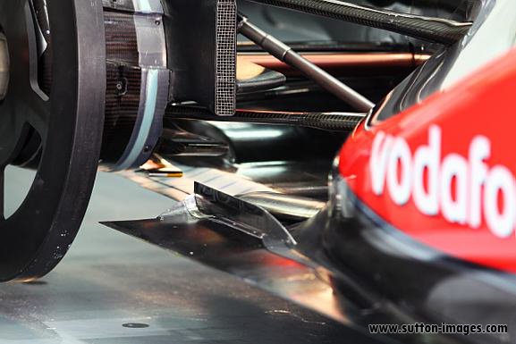
Diffusers are connected to flat floor with a radius, but that radius is small; it is more similar to the photograph posted by marekk than to the cad image. Webber flip up of last year could give some evidence.
I think there is also a rule limiting that radius, and ferrari found a loophole around that since 2001.
Advice: do not be so aggressive when you write sentences that could prove wrong, as you did in your post.