I thought I would take the time to also show the system used in the Peugeot V10 F1 engine that member E36Jon posted on page 13.
It is the same style system as in the start of this thread - as in a bucket tappet system - direct acting off the lobe - no finger follower.
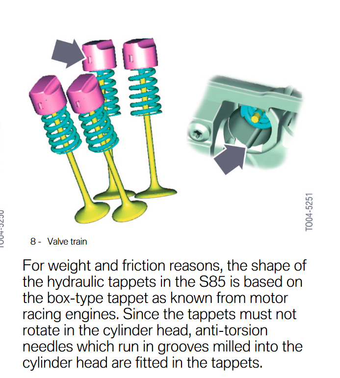
The one difference with this system is the barrel itself is all steel, and the tappet has a crowned roof which the cam acts on. The crowned roof allows a more aggressive cam. A normal flat tappet does not allow such an aggressive lobe since the lobe starts to contact the tappet perimeter edge after a certain point.
Some parts are DLC coated - because the tappet is crowned it cannot be allowed to rotate. So, there are two index tabs on the inside of the bucket tappet that locate in slots on the outside of the barrel. These index tabs stop the bucket tappet from rotating under the lobe. This crowned tappet system is semi common now from memory, and can be seen on the Bmw M3, or the E60 M5 - not pneumatic though obviously.
The complete assembly can be seen below,
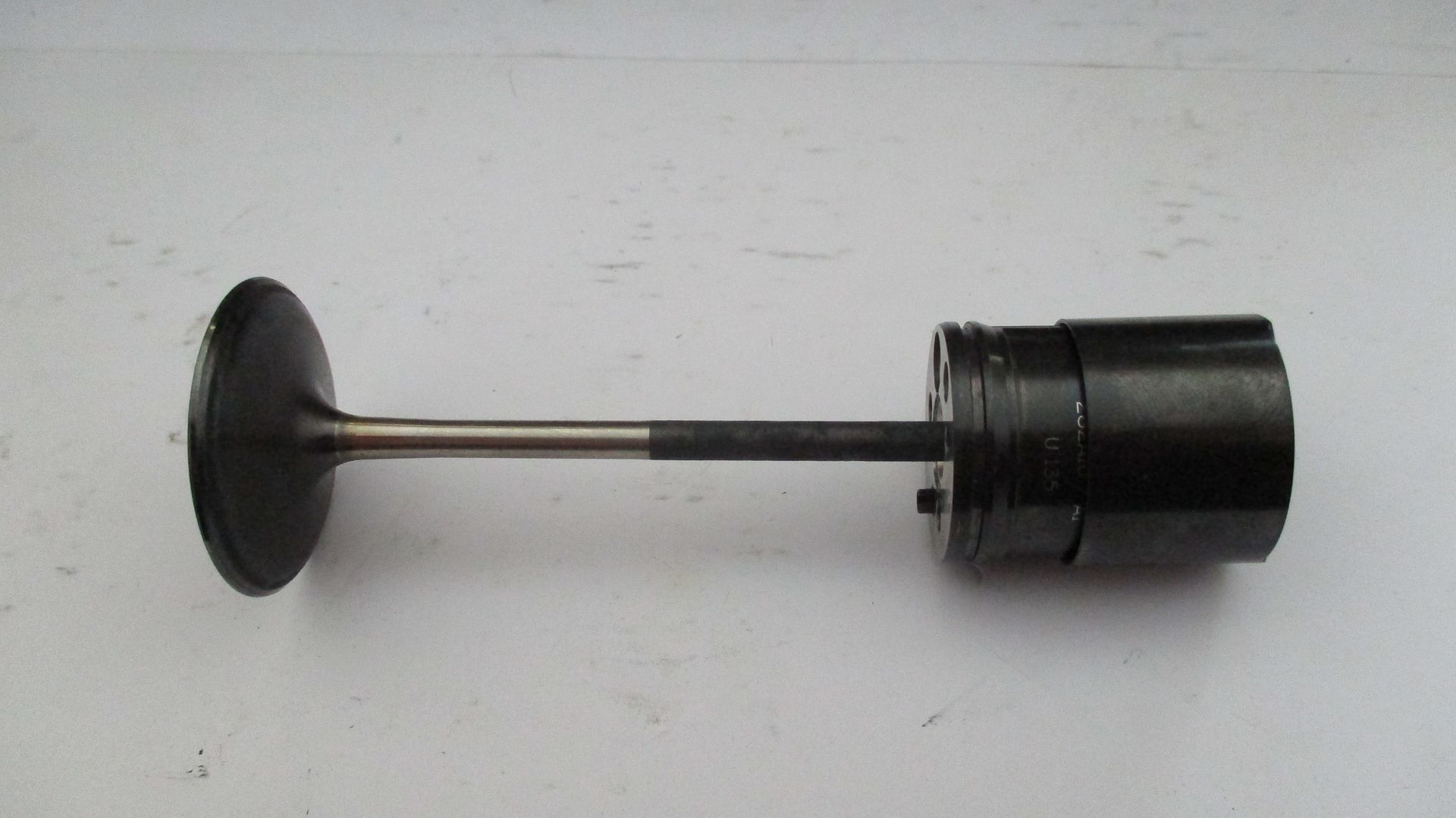
It comprises of the valve, valve collets, lash cap, barrel, bucket tappet, and the piston plunger + seals.
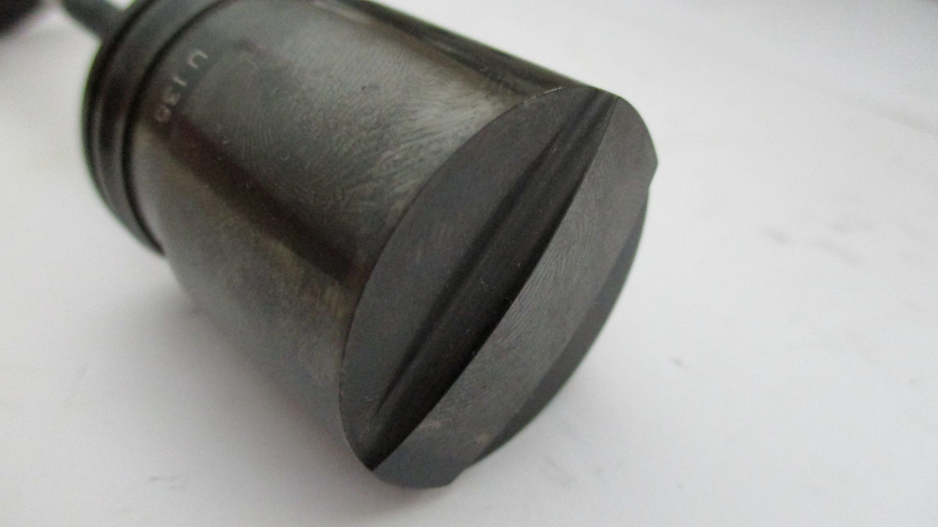
The crown detail,
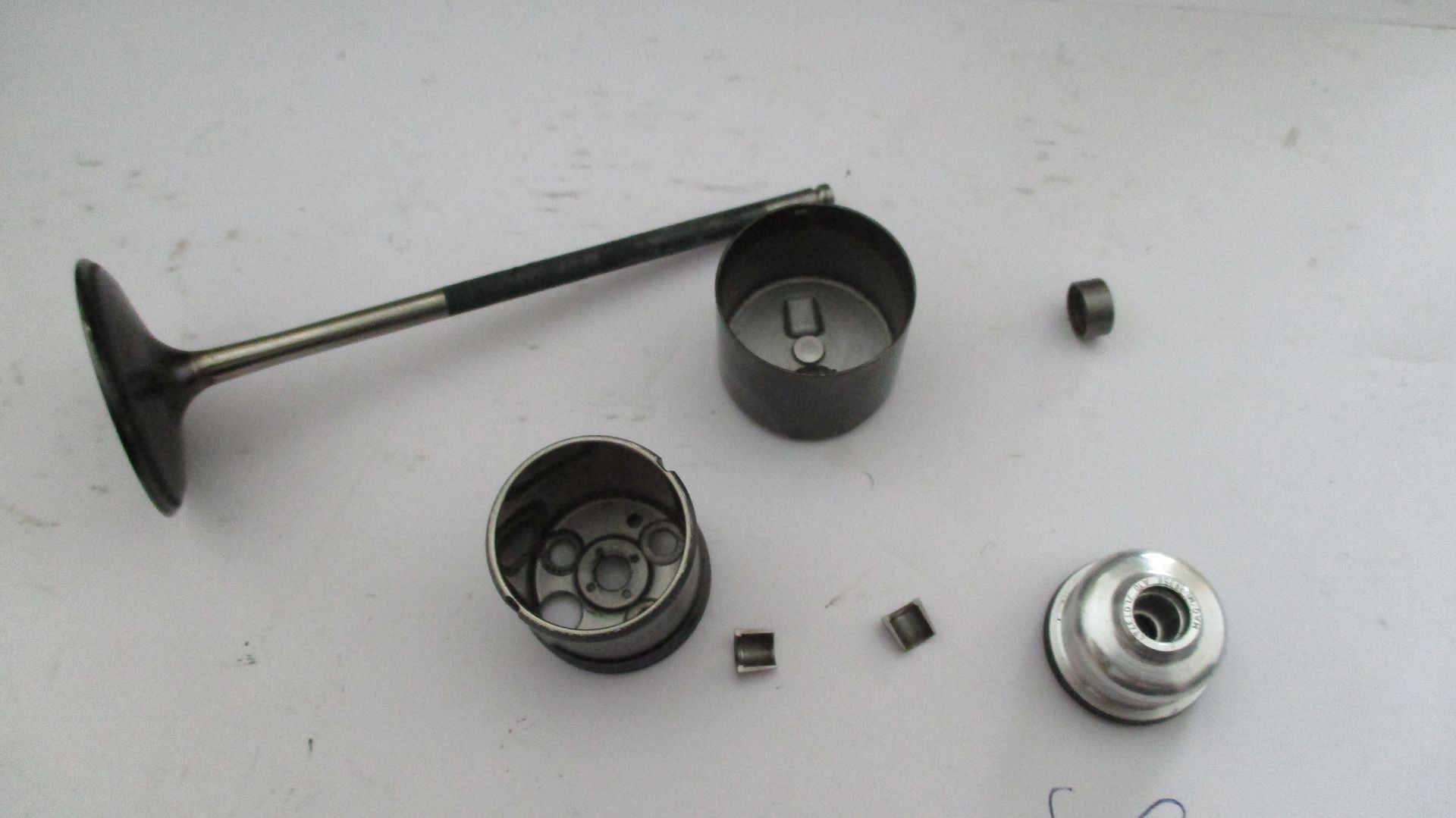
The main parts,
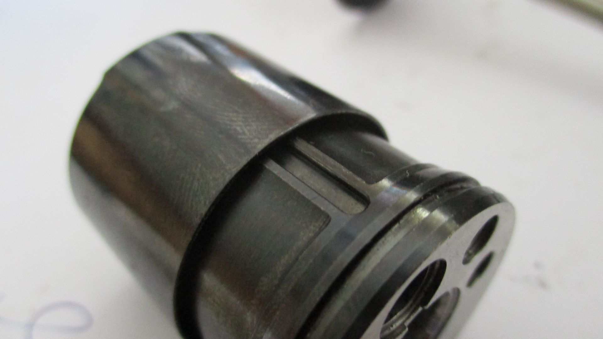
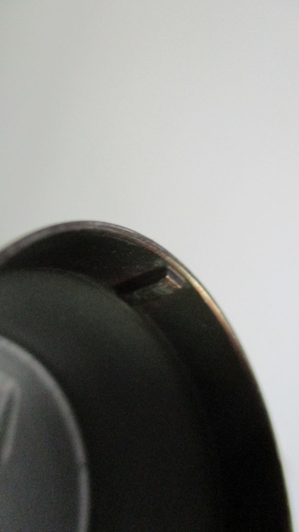
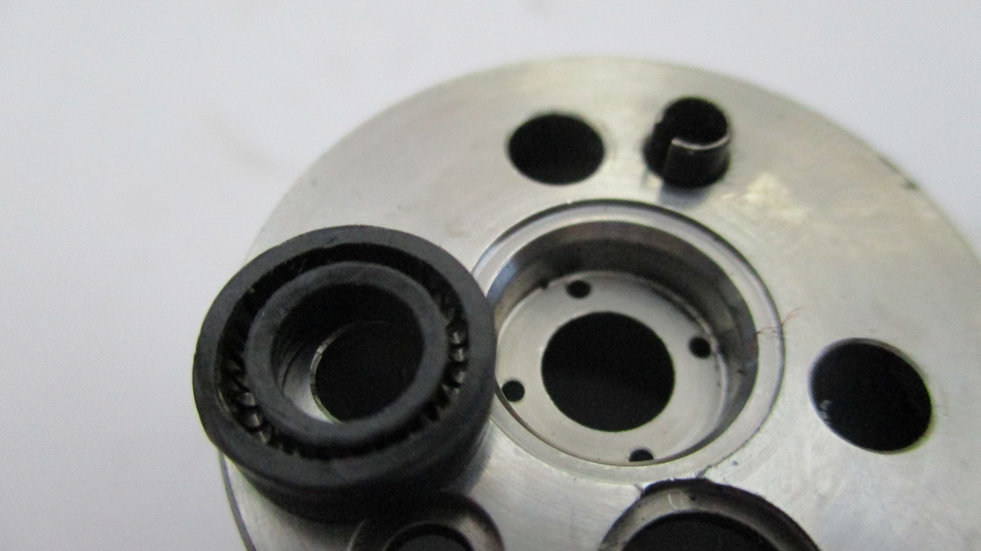
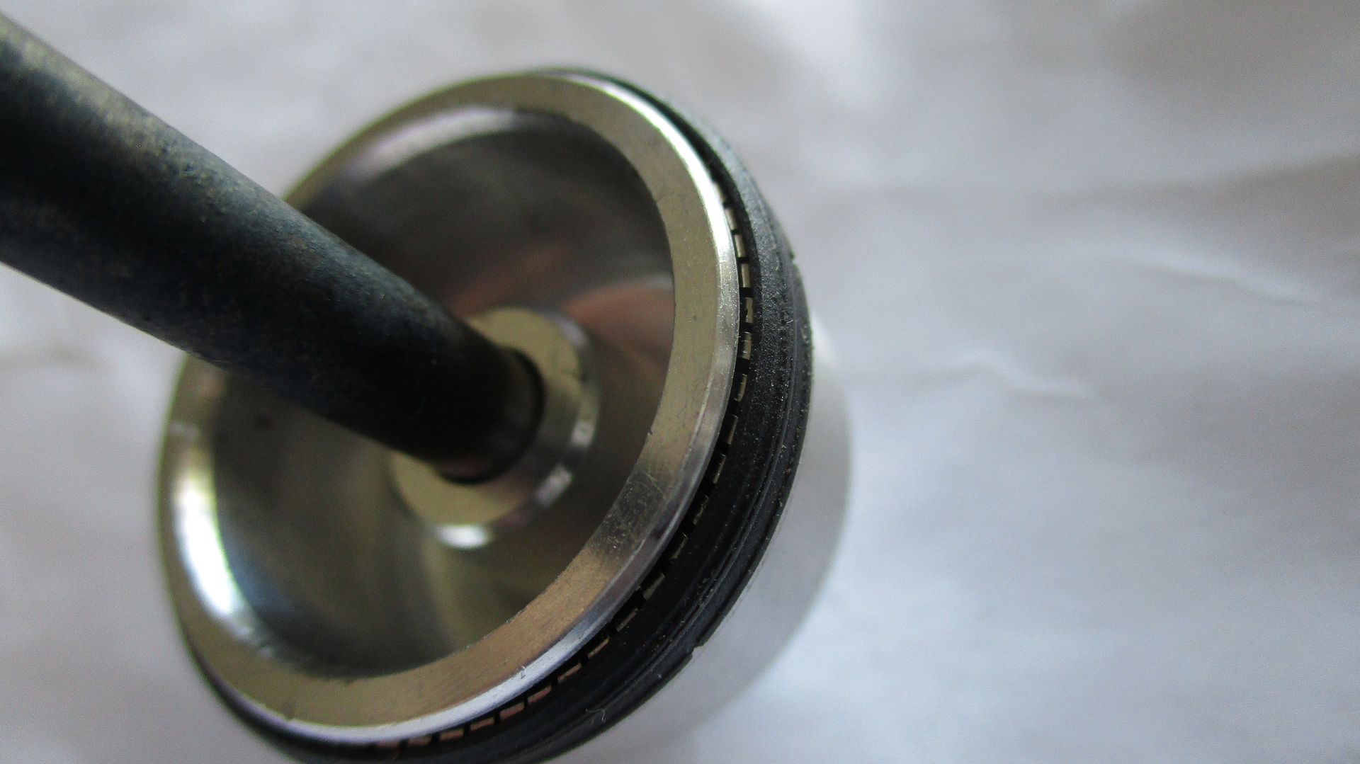
The index slot detail on the barrel wall,
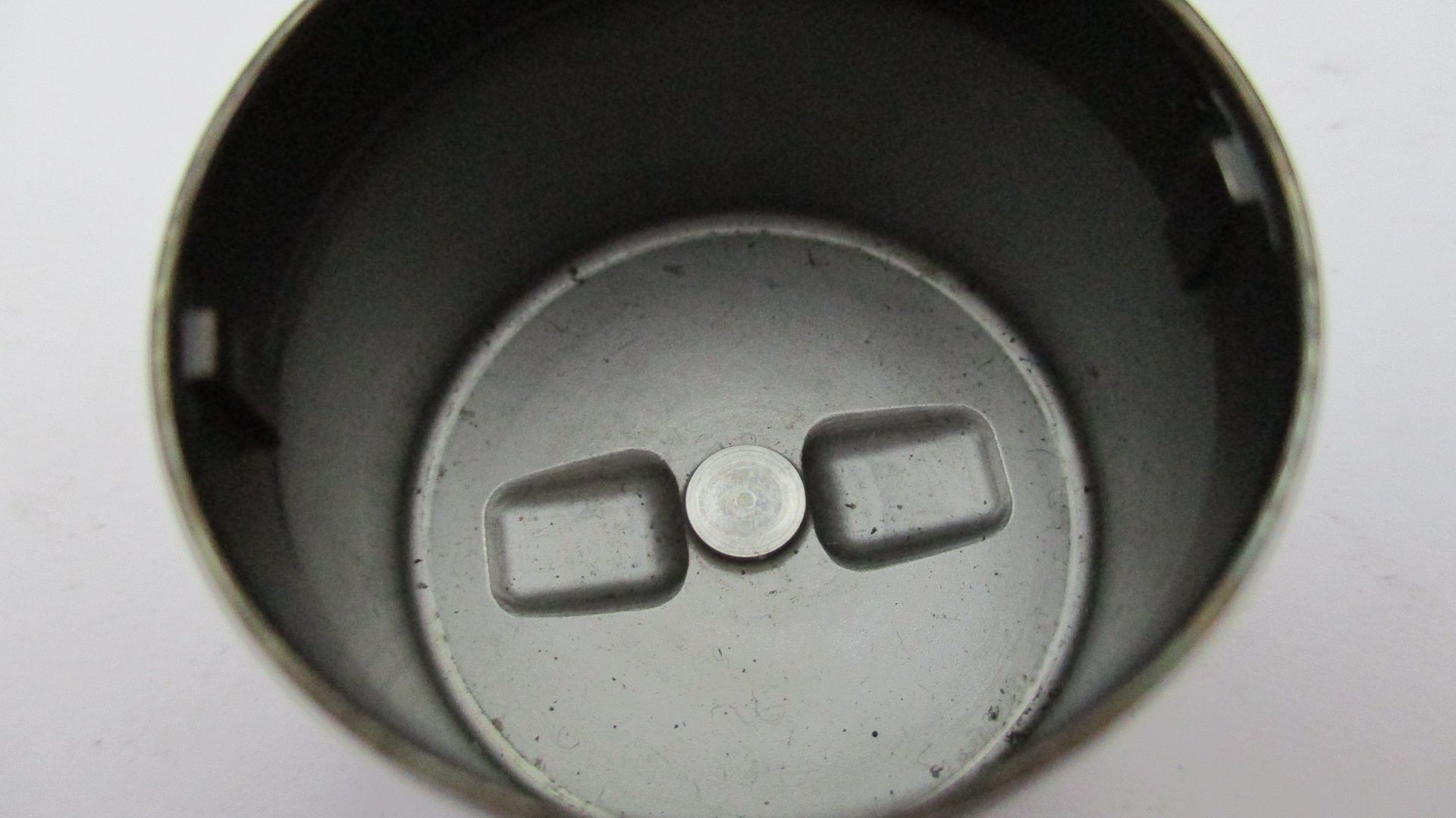
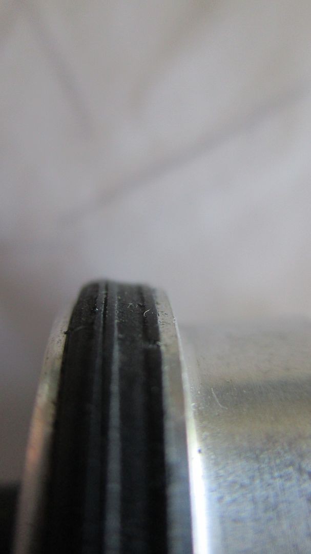
The mating tab on the bucket tappet, and also the area that sits on the lash cap,
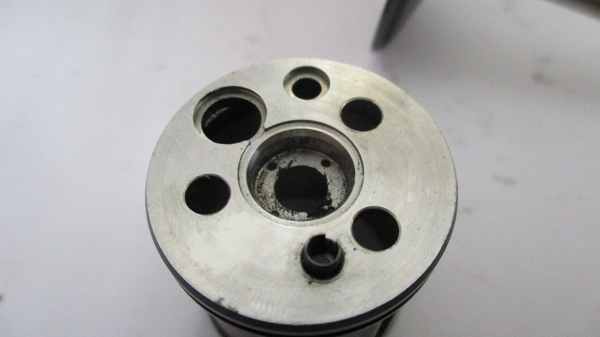
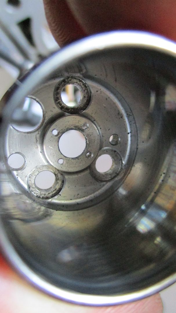
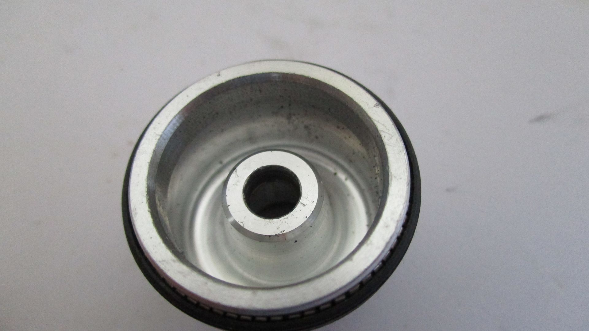
The interior of the steel barrel - three bolt down holes plus air holes, also notice the 4 small air holes at stem area. These holes allow pressurized air from the barrel to travel down to the valve stem seal. This air pressure energizes the lip seal making it 'air tight' against the 5mm valve stem,
The seal - seal inverted to show lip area,
Onto the piston plunger now, its an aluminium part and pretty simple in form,
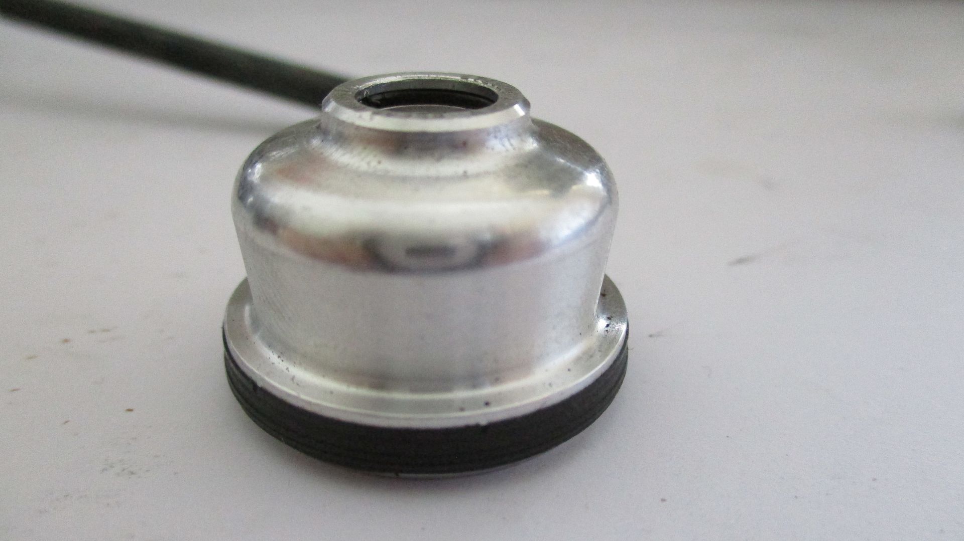
There are three seals in total on this part - the main air piston seal, a valve stem o-ring seal on the under side, and a lash cap o-ring seal on the top side.
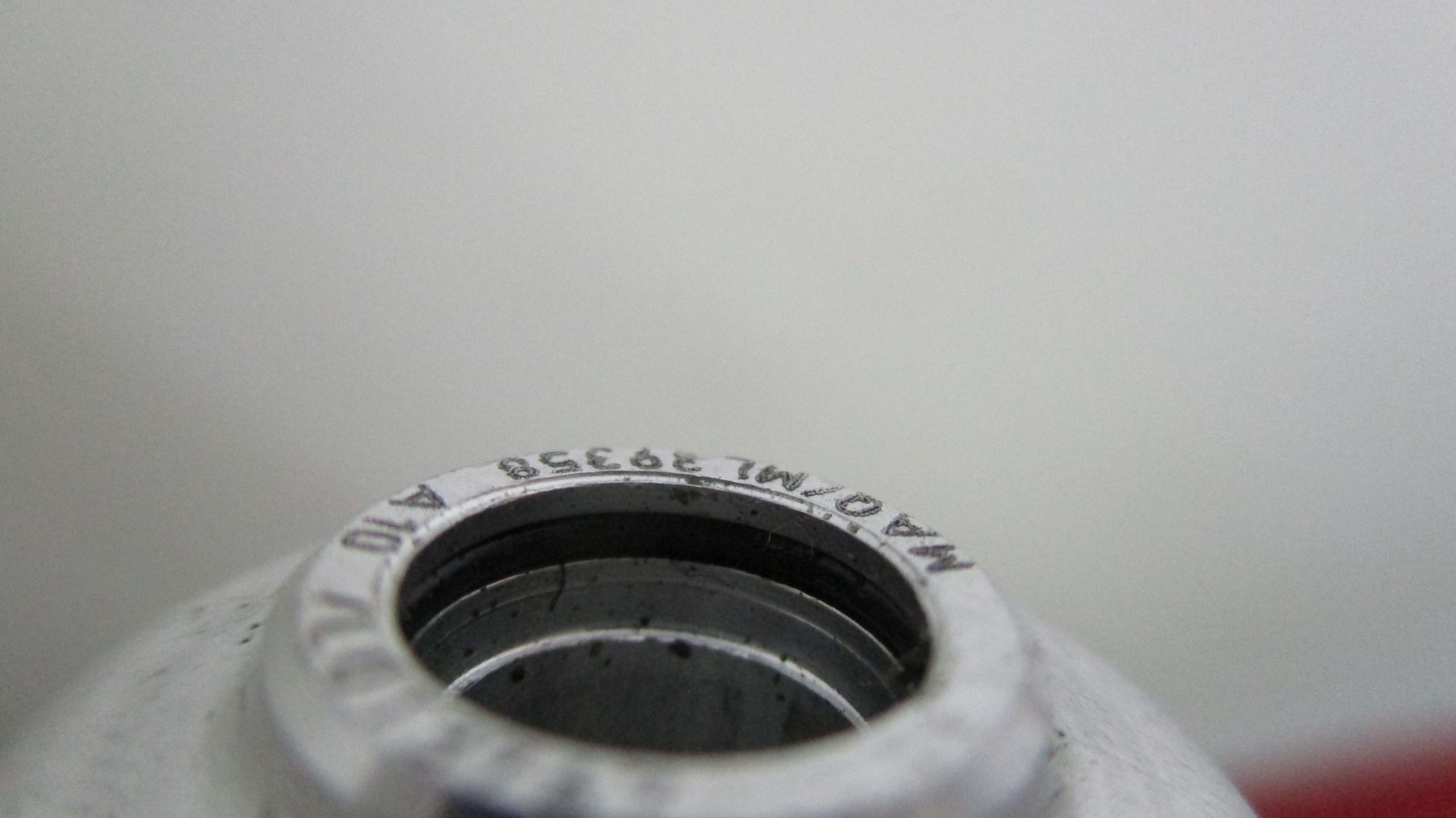
A closer look at the lash cap o-ring seal. The lash cap picture in the group photo at start of thread is just a small hardened disc that sits ontop of valve stem, and is what the bucket tappet bears down on. These lash caps can be ground to set clearances.
The stem seal is housed down in the piston plunger - a poor shot and hard to capture,
A shot of the spring energized main plunger seal,
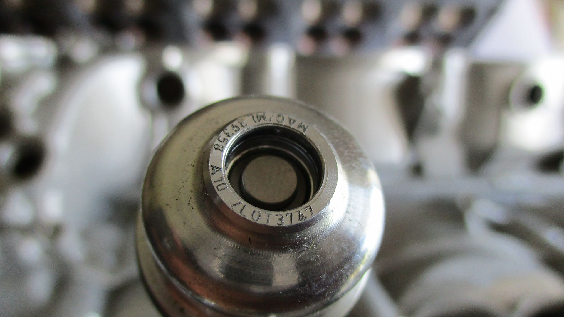
And lastly, a shot showing valve and collets fitted - the lash cap then locates down in this bore, and is sealed with the o-ring shown.
That concludes this piece. I think as mentioned before it is great to see all these different systems and styles. I was always intrigued by them and set out about 5years ago to locate them, see how they worked and display all. Its taken me to many parts of the world looking for them, and has been a huge effort as its nearly impossible get your hands on them, or even any info.
I think now that I'm happy to park my findings on them - in this thread you will find the very early style, this style above, and onto the modern high rpm Cosworth V8 finger follower style item. The one thing common in them all is the seal styles.
Here is a link to the Cosworth V8 finger follower style item mentioned above incase you missed it,
viewtopic.php?f=4&t=24821
Enjoy,
Brian,