2 stroke thread (with occasional F1 relevance!)

All that has to do with the power train, gearbox, clutch, fuels and lubricants, etc. Generally the mechanical side of Formula One.
manolis
107
Joined: 18 Mar 2014, 10:00

Re: 2 stroke thread (with occasional F1 relevance!)

Post

Hello Tommy Cookers

You write:
“again ....
the Gen H-4 has a lot of rotor coning
put there to contribute stability”


The rotor coning of the GEN-H4 makes a difference in stability only on or near the ground. If the one side of the GEN_H4 elevates for a few inches relative to its opposite side, the aerodynamic force on each rotor blade maximizes each time it passes from the lower region of its path and minimizes after 180 degrees when it passes from the higher region of its path, away from the ground and looking somewhat to the side; a torque is created that restores the vehicle to a more upright / vertical position.

Above some height, say 5 - 10m, the rotor coning cannot improve stability.
In other words, if you lock the joint between the upper assembly (comprising the engines and the rotors) and the lower assembly (where the pilot and the fuel tank are) and “freeze” the pilot, the Gen_h4 will turn and fall to the ground as the rocket of the “Pendulum rocket fallacy” article.


You also write:
“try this ....
www.nar-associates.com>cruise_propeller_efficiency_screen.pdf
or try searching for Propeller Efficiency - NAR Associates
it contains a full propeller performance diagram
it seems to show how hover power requirement is high (for PF-type speed range without ideal pitch variability).


The Portable Flyer as a transportation means will take-off vertically and in a few seconds it will turn to high-speed horizontal cruise till its destination where it will turn again to land vertically (in a few seconds again).

More than 90-95% of the time it will be in horizontal cruising with the propellers / rotors / engines revving / operating at their optimum.

When it is necessary to hover (say, during a rescue, or for demos etc) it can; but in such cases the efficiency is not important.

Thanks
Manolis Pattakos

User avatar
PlatinumZealot
550
Joined: 12 Jun 2008, 03:45

Re: 2 stroke thread (with occasional F1 relevance!)

Post

J.A.W. wrote:
14 Mar 2020, 01:32
^ OO7, as it happens - that Spanish "One stroke" engine was featured
recently among the 2020 2T Conference presentations - but other 2T's there
were more impressive, & thus likely of more interest for 'Future F1' potential.

Link to the 2020 2T Conference presentations, below:

https://drive.google.com/drive/folders/ ... wFXLrhjPH9
Is it only semantics why this thing is a one stroke? Like divide the 2 strokes by 2 rotations or something like that?
🖐️✌️☝️👀👌✍️🐎🏆🙏

manolis
107
Joined: 18 Mar 2014, 10:00

Re: 2 stroke thread (with occasional F1 relevance!)

Post

Hello all.

Here is the plan:

Image

and here is where we are now:

Image

The four white sprockets are plastic PLA (3D printed); they are to be made of aluminum A356 cast, and their teeth be machined with a CNC milling machine.


The propellers will be bigger: 43” (110cm) in diameter instead of 39” (99cm) of the initial design.

Thanks
Manolis Pattakos.

User avatar
Big Tea
99
Joined: 24 Dec 2017, 20:57

Re: 2 stroke thread (with occasional F1 relevance!)

Post

manolis wrote:
19 Mar 2020, 16:13
Hello all.

Here is the plan:

https://www.pattakon.com/Fly_files/Port ... ission.png

and here is where we are now:

https://www.pattakon.com/Fly_files/Port ... elts_1.jpg

The four white sprockets are plastic PLA (3D printed); they are to be made of aluminum A356 cast, and their teeth be machined with a CNC milling machine.


The propellers will be bigger: 43” (110cm) in diameter instead of 39” (99cm) of the initial design.

Thanks
Manolis Pattakos.
I know very little about it, but what happens at the point the rotors pass eachother? that must be supersonic??
When arguing with a fool, be sure the other person is not doing the same thing.

gruntguru
563
Joined: 21 Feb 2009, 07:43

Re: 2 stroke thread (with occasional F1 relevance!)

Post

What matters is the velocity of the rotor relative to the air that is passing over it. Think of the air as moving vertically downwards (approx) and the rotor slicing through it like a bolt through a nut.

The rotor above does impart SOME rotation to the air column but not enough to significantly affect the relative velocity through the lower rotor.
je suis charlie

manolis
107
Joined: 18 Mar 2014, 10:00

Re: 2 stroke thread (with occasional F1 relevance!)

Post

Hello all.

In the following photo:

Image

the hollow part (it seems as having four "legs") between each pair of OPRE Tilting engines (better shown in the three standing Portable Flyers) serves as the connector of each pair of engines, also as the "cylinder head" of the inner scavenge pumps, also as the tensioner of the long tooth belts.

The covers at the two ends of each Portable Flyer serve as "cylinder heads" of the outer scavenge pumps, they also serve as supports whereon two pipes are secured; on teach pipe are rotatably mounted the big sprockets / propellers (the one above the Portable Flyer, the other below).

Thanks
Manolis Pattakos

User avatar
Big Tea
99
Joined: 24 Dec 2017, 20:57

Re: 2 stroke thread (with occasional F1 relevance!)

Post

gruntguru wrote:
20 Mar 2020, 01:45
What matters is the velocity of the rotor relative to the air that is passing over it. Think of the air as moving vertically downwards (approx) and the rotor slicing through it like a bolt through a nut.

The rotor above does impart SOME rotation to the air column but not enough to significantly affect the relative velocity through the lower rotor.
When watching a 'copter in the rain the vortex seems to 'slide' allong the blade and roll off the tip. If it has been 'removed' from the path of the approaching blade, would than not mean the air there is less dense?
When arguing with a fool, be sure the other person is not doing the same thing.

Tommy Cookers
617
Joined: 17 Feb 2012, 16:55

Re: 2 stroke thread (with occasional F1 relevance!)

Post

the vortex is visible because its pressure is less than ambient - presumably density change isn't the main event

though it's always said that in principle efficiency is greater with fewer blades

User avatar
PlatinumZealot
550
Joined: 12 Jun 2008, 03:45

Re: 2 stroke thread (with occasional F1 relevance!)

Post

manolis wrote:
20 Mar 2020, 09:28
Hello all.

In the following photo:

https://www.pattakon.com/Fly_files/Port ... s_Four.jpg

the hollow part (it seems as having four "legs") between each pair of OPRE Tilting engines (better shown in the three standing Portable Flyers) serves as the connector of each pair of engines, also as the "cylinder head" of the inner scavenge pumps, also as the tensioner of the long tooth belts.

The covers at the two ends of each Portable Flyer serve as "cylinder heads" of the outer scavenge pumps, they also serve as supports whereon two pipes are secured; on teach pipe are rotatably mounted the big sprockets / propellers (the one above the Portable Flyer, the other below).

Thanks
Manolis Pattakos
I have been thinking...

You have these things..
A new type of engine
A new type of flyer

The engine is not proven nor optimised yet to fulfill its potential. They are I suppose better power to weight engines out there, and this is is OK it is expected. The engine willbe improved with time and investment.

The flyer is not proven nor optimized yet. I have not done the research to categorically say if your flyer is the best verticalflyer out there yet.... But that is OK. It can be improved....

Now, what I have been bitten by in the past is building both and engine and vehicle at the same time. And i failed to get the engine going (gas turbine, with power shaft) and so i did not get to test the vehicle.. Looking back i should have only focused on optimizing one at a time.

My question to you is this... What if you complete one at a time. I think both are great ideas. What do you think of testing the flyer with an already optimized engine to prove the concept of the flyer? Or even building a small scale flyer for testing? OR build the engine on a test bench and optimize the materials and geometry to learn the efficiency, oil consumption, emmisions, power, wear etc? Because I have some doubt if an un-optimized engine willhave theperformance to liftthe flyer. :?:
🖐️✌️☝️👀👌✍️🐎🏆🙏

manolis
107
Joined: 18 Mar 2014, 10:00

Re: 2 stroke thread (with occasional F1 relevance!)

Post

Hello PlatinumZealot.

The Portable Flyer is actually its engines.

A couple of days ago I answered to the “same” question in another Forum, wherefrom the following quote is:


You write:
Wouldn't it be a *lot* easier to do proof of concept testing using off-the-shelf pieces? Use a conventional small engine, pulleys, etc.


It depends on what you mean “proof of concept”.
If you mean to prove that you can lift a weight by two counter-rotating propellers, yes, it would.

But the Portable Flyer project is different.
And is based “entirely” on its OPRE Tilting engines, which were designed for this specific use.

Here is how the “Device Technical Report” (at https://www.pattakon...oFly/index.html ), as filed in the GoFly / BOEING contest, begins (the bold letters are from the original document):
  • “PORTABLE FLYER ARCHITECTURE AND BASIC DESIGN CHARACTERISTICS

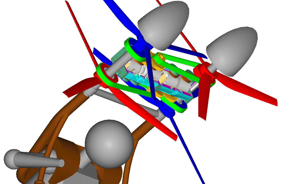
    The PORTABLE FLYER comprises two OPRE Tilting Engines secured to each other to form (with their casings) the personal flying device’s “backbone”.

    The one engine drives two counter-rotating propellers arranged above the backbone, the other engine drives two counter-rotating propellers arranged below the backbone.

    The following presentation deliberately focuses on the engines because the PORTABLE FLYER is actually its engines. The goal is the development of a new kind of “passé partout” useful transportation means uncompromised on: safety, easy use, range, speed, mileage, emissions, ownership/running cost and portability (wearable).

    At the ends of the backbone they are secured two “vertical” pipes whereon the propellers are rotatably mounted. . .”

If you know a small engine and “pieces off-the-shelf” that could replace the OPRE Tilting engines of the Portable Flyer, please let me know.

But there are several requirements from such ready engines:
  • You need to carry a pair of them (for safety). So they have to be lightweight (no more than 10Kg / 22lb each), because the Portable Flyer has to be wearable: pilot’s legs / feet are the only landing gearing.

    They have to have high specific power (say around 5kW/Kg).

    Each engine has to share equally its power on two counter-rotating synchronized crankshafts, each driving its own propeller.

    Each engine has to be true vibration-free because it has to be directly secured / supported on pilot’s body.

    Each engine has to have zero reaction torque: on the air the pilot has nowhere to abut on or to be supported on; the slightest unbalanced torque from the propulsion unit may prove catastrophic; any reaction torque (say at an abrupt opening or closing of the throttle, or at a misfire) may prove fatal.

    Each engine has to have zero gyroscopic rigidity, otherwise the pilot will need a lot of thinking, a lot of effort and a lot of time to re-vector the thrust. Only with zero gyroscopic rigidity the control becomes easy, direct and intuitive, making the training of beginners easy, safe and fast.
So, is there in the market such engine / off-the-shelf parts?


You also write:
It's not like the novel engine design will be significantly lighter or more powerful than stuff that's readily available.


The engine that makes the Portable Flyer is more than just a “significantly lighter or more powerful engine”.


You also write:
“Whether the general concept is sound, it should obvious be pretty quickly . . . You obviously lack the resources to do it the way you want to”

and here is what you write in the "Koenigsegg" thread:

“ The Hyundai VVT system, however, is quite clever, gets most of the theoretically possible upsides, and it actually exists in numbers.”


I think you mean the Hyundai CVVD (Continuously Variable Valve Duration) system.

While I obviously lack resources to proceed “quickly” with the Portable Flyer project, Hyundai does not lack resources; in Hyundai they have everything, from experience, to know-how, to machinery, to materials, to staff, to funds, to test facilities, to budget (presumably no budgetproject).

Here is the first page of Hyundai’s CVVD US-patent:

Image

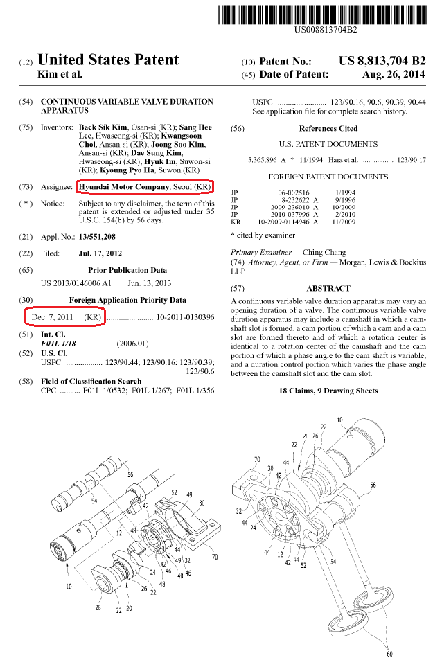
The CVVD mechanism was designed 9 years ago, and only a few months ago it was used in a mass production car.
And the CVVD of Hyundai is a simple cam-control mechanism.

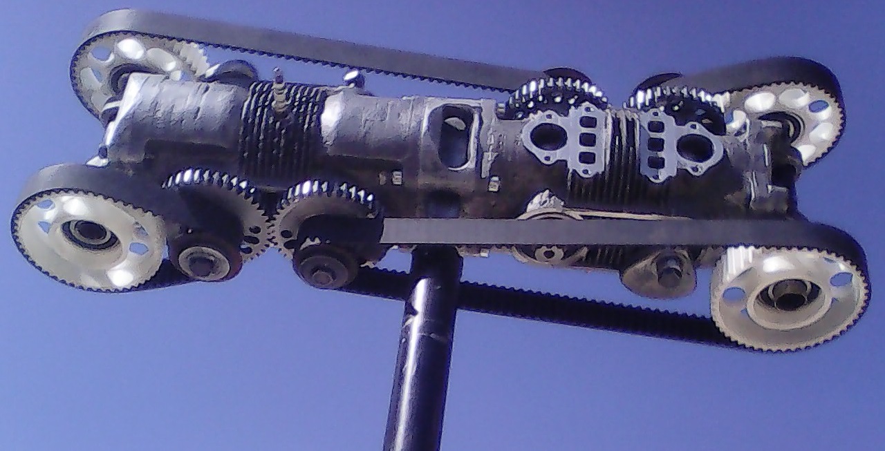
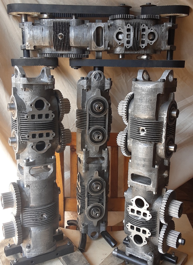
The Portable Flyer is a “start from scratch” project.
Excluding the roller bearings and the piston rings, everything else is hand made.


PS:
It will be interested to open a new thread to discuss about the “Breakthrough Engine that Answers a 133-year Challenge” (!!!) Hyundai claims.

Thanks
Manolis Pattakos

Rodak
35
Joined: 04 Oct 2017, 03:02

Re: 2 stroke thread (with occasional F1 relevance!)

Post

There is no way to control this thing. Suggestions to build a model with another engine system are good, as the issue of control could be investigated and, maybe, solved. Yeah, I know, you will post some drawings of bodies flying across the sky, but the reality is there is no mechanism for controlling the machine. With a hang glider or wing suit changes in c.g. can steer the machine, but you have no way to apply torque to change the position of the engine unit. Until you solve that this is a death machine. Yeah, you'll post a verbal rebuttal with pictures of a body hanging down from the rotors etc. etc. but this is not the reality. The 'pilot' has to have a mechanism of control and as you demonstrate there is no such thing. You don't have power to sustain horizontal flight, and I don't see any controls for throttle, etc.

All your 'pictures' show the pilot with his hands and legs flying about. How are the engine controls to be used? What sort of data does the pilot have? How does the pilot get flight information? Is there any sort of horizon? Maybe a bit of testing would be useful. You don't even know if this thing will be stable. I agree a vertical takeoff might be possible, but after that..... There is no control for yaw, pitch, or attitude except some words..... I am not new to this game and this is a disaster waiting for the first flight to happen. You have not demonstrated any stability calculations except to aver that the pilot will be able to fling his or her legs about and somehow achieve flight. Damn.

manolis
107
Joined: 18 Mar 2014, 10:00

Re: 2 stroke thread (with occasional F1 relevance!)

Post

Hello Rodak.

At the middle of the previous page it is the "Pendulum rocket fallacy" article of Jim Bowery.

Please re-read it and let me know your objections, if any.

Thanks
Manolis Pattakos

Pinger
9
Joined: 13 Apr 2017, 17:28

Re: 2 stroke thread (with occasional F1 relevance!)

Post

manolis wrote:
19 Mar 2020, 16:13
Hello all.


The four white sprockets are plastic PLA (3D printed); they are to be made of aluminum A356 cast, and their teeth be machined with a CNC milling machine.
Cheaper and easier to source existing camshaft sprockets - surely?

manolis
107
Joined: 18 Mar 2014, 10:00

Re: 2 stroke thread (with occasional F1 relevance!)

Post

Hello Pinger.

You right:
"Cheaper and easier to source existing camshaft sprockets - surely?"

No.

Each sprocket is to be rotatably mounted by roller bearing(s) on one of the two side pipes of the Portable Flyer (by the side pipes the pair of the two engines are secured to the saddle; through these side pipes they pass the fuel and the control (gas cable etc) to the engines).

Each sprocket of the Portable Flyer passes half of the power of the engine. A crankshaft sprocket passes only the power required to open the valves of the engine (typically: less than 1kW).

Another "cheaper and easier" solution would be the sprockets used in the "belt / sprockets" final transmission of motorcycles.
But, again, you have to find the proper size / form, and then you have to modify and support it.

At the end, it appears “cheaper and easier” (i.e. better) to start from scratch and make the parts as you want them to be.


Worth to mention:

While you can choose the width of the tooth belt as you like (say, 25mm, 27mm, 28.5mm,40mm,100mm etc) the number of teeth (which defines the "pitch" length) of the available tooth belts is not increasing one by one:

Image

For instance, if the belt with the 120 teeth is short, your only option is to go to 130 teeth, which means (130-120)*8mm = 80mm longer pitch length, or some 40mm longer axis-to-axis distance).


By the way, is it clear how the belts of the Portable Flyer are tensioned?

Thanks
Manolis Pattakos

Tommy Cookers
617
Joined: 17 Feb 2012, 16:55

Re: 2 stroke thread (with occasional F1 relevance!)

Post

https://en.wikipedia.org/wiki/Light-sport_aircraft
seems to imply currently an 'LSA' market for an alternative ie 2 stroke engine

Post Reply