Page 8 of 13
Re: How is the engine/gearbox assembly mounted to the tub?
Posted: 24 Nov 2010, 19:53
by 747heavy
how about this for an (a bit simplyfied) way to look at it?


Re: How is the engine/gearbox assembly mounted to the tub?
Posted: 24 Nov 2010, 20:06
by 747heavy
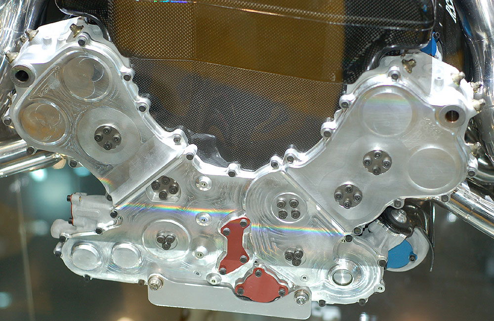
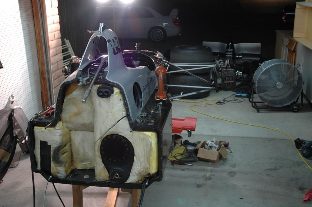
thanks for the photo´s endless
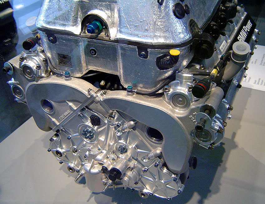
Unfortunately they show (like my one from the Ferrari engine) the engine bellhouse interface.
Nevertheless, it can be seen, that they use dowel´s to take the shear load of the bolt.
Another thought just crossed my mind.
Do we make a wrong assumption when we compare the engine with an solid aluminium(cast) block?
What about the head gasket?
I know the idea is maybe a bit far fetched, but what if we use the force generated by the extansion of the engine to keep our head gasket compressed when temperature increases?
Could be way off, but I just wanted to put the idea out there to see what you guys think about it.
Cheers
Re: How is the engine/gearbox assembly mounted to the tub?
Posted: 24 Nov 2010, 20:42
by ringo
747heavy wrote:how about this for an (a bit simplyfied) way to look at it?
Oh i see what you did!

I was a bit confused at first. It's an interesting way at looking at it yes, but the Engine would put a uniformly distributed load on the bolt.
You would have to use this equation: end deflection = PL^3/8EI
P is the side load on the bolt, L is length and E is young's modulus, I is the Ixx of the bolt.
Ixx of a circle is pi D^4/64
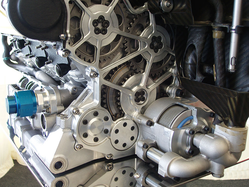
That clamp pressure is so high though, i think if there is any motion it would be stretching in the body of the engine, but no sliding at the clamping interface, now that we can conclude that dowel bushings are used, which is a physical barrier to any sliding at the interface.

Thanks to endless for these pics. They are very revealing. It's gearbox side, but i saw the dowel recesses on the other face as well.
Re: How is the engine/gearbox assembly mounted to the tub?
Posted: 25 Nov 2010, 00:48
by endless
747heavy wrote:Unfortunately they show (like my one from the Ferrari engine) the engine bellhouse interface.
Nevertheless, it can be seen, that they use dowel´s to take the shear load of the bolt...
ringo wrote:...They are very revealing. It's gearbox side, but i saw the dowel recesses on the other face as well.
Here you are

Re: How is the engine/gearbox assembly mounted to the tub?
Posted: 25 Nov 2010, 01:01
by 747heavy
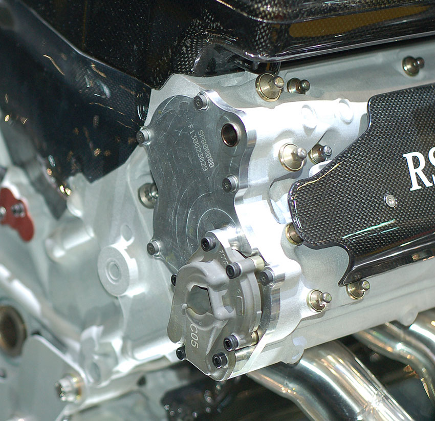
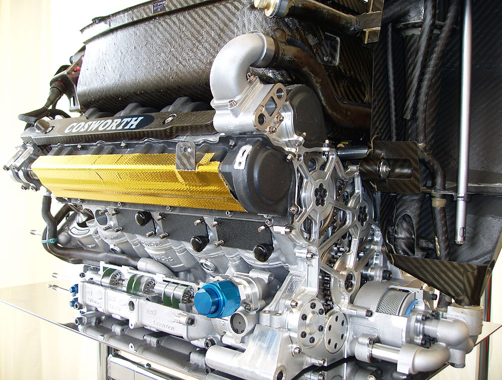
you are >>> The Man <<< mate - cheers
and surprise, no dowel recesses, but hardened steel insert at the top fixing points
and, if my eyes don´t fail me, some fretting marks !??! (but I could be wrong)
Re: How is the engine/gearbox assembly mounted to the tub?
Posted: 25 Nov 2010, 01:09
by marcush.
those steel shouldered sleeves have a fixation screw at the outer perimeter...so it can be savely assumed there is no press fit for the sleeve?
I´d assume they supply the give in this application and let the longstuds take tup the small bending load load?
Re: How is the engine/gearbox assembly mounted to the tub?
Posted: 25 Nov 2010, 01:24
by ringo

Inserts are more like a type of washer that sits in a recess. That hole is not blind, i goes through to the other side.
I have no clue what purpose they serve.
Re: How is the engine/gearbox assembly mounted to the tub?
Posted: 25 Nov 2010, 01:44
by marcush.
to me these black inserts are like washers sitting in those recesses provided by the machined countersunk in the head .
The two small fixation screws are placed startegicallly to allow the needed movement along the axis of the cylinderbore so I think the steel inserts are a loose fit in the cylinderhead (with say some .5mm degree of freedom in that direction .)When torquing the engine reataining nuts to the studs around 100mm away from the mounting face the nut face towards the cylinderhead does not really need to slip for allowing the engine grow shrink to be acomodated the bolt could maybe bend enough to accomodate the dimensional change..
Re: How is the engine/gearbox assembly mounted to the tub?
Posted: 25 Nov 2010, 02:40
by endless
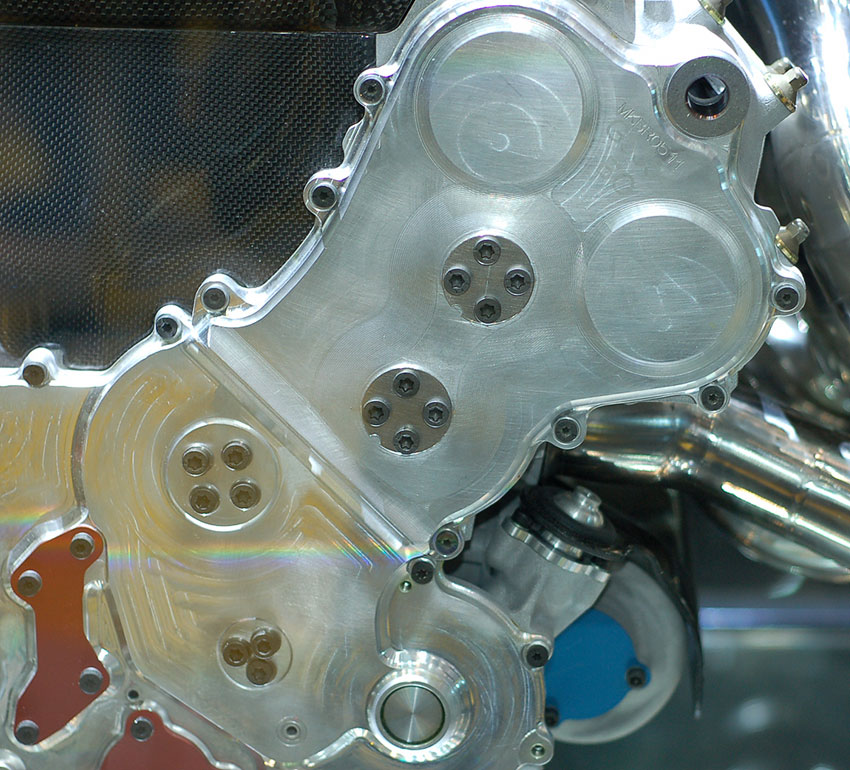
The above pic in higher res:
http://i52.tinypic.com/2rrxsn4.jpg
Sorry for not posting this earlier.
Keep up the nice talk! =D>
Re: How is the engine/gearbox assembly mounted to the tub?
Posted: 25 Nov 2010, 04:49
by riff_raff
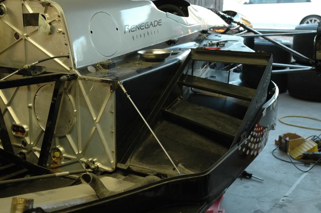
Just to add more confusion to this very interesting topic, here's a picture of the rear bulkhead on a Swift Champ Car tub. It's an aluminum plate bulkhead that is bolted around its perimeter to the carbon/epoxy tub (the reason it is removable is for installation of the large fuel bladder used on Champ Cars).
Regards,
riff_raff
Re: How is the engine/gearbox assembly mounted to the tub?
Posted: 25 Nov 2010, 09:26
by xpensive
Thought I'd give up on you ringo, but you remind me of a couple of "draftmen" who were working for me in the US.
Things were fine until they took some engineering night-classes, which prompted them to do wild calc's at the office,
driving me completely out of my mind...
ringo wrote:
...
A spring rate of 60,000N/cm is also pretty much a brick wall,more stiffness than that carbon tub could provide.
...
Anyway, you give it away by using strange units like the above and it doesn't mean --- really.
- That 400 mm long, 50 mm Alu bar I used while trying to xplain, would have a "spring rate" of 3 450 000 "N/cm".
- A skinny 8 mm steel pin-bolt with 50 mm free length, perhaps like in the Cosworth images, should be in the region of
2 000 000 "N/cm", but very flexible laterally, which is the general idea when it comes to cope with thermal xpansion.
Re: How is the engine/gearbox assembly mounted to the tub?
Posted: 26 Nov 2010, 17:31
by ringo
I gave you an example with inches and with no springs at all.
I am not an american, I am from the caribbean, we use SI units.
I wouldn't give a spring rate in N/m if i am dealing will cm sized components. My lecturer taught in N/cm2 as well, so i got used to doing that, and i find it more representative than other units. The american system is to bulky and inflexible.
You can't draw back the curtains and give me up, because I am not trying to fool you.
I may very well use 1 million N/cm and the only thing that changes is that i get more restraint.
60,000 N/cm is 34,260 lb/inch
- That 400 mm long, 50 mm Alu bar I used while trying to xplain, would have a "spring rate" of 3 450 000 "N/cm".
- A skinny 8 mm steel pin-bolt with 50 mm free length, perhaps like in the Cosworth images, should be in the region of
2 000 000 "N/cm", but very flexible laterally, which is the general idea when it comes to cope with thermal xpansion.
All the better for me.
This just makes things easier to prove. The only reason i used a spring instead of another bar, is that i would have to consider the expansion of the other bar as well, then i would have to to a deeper calculation, and no one would bother trying to get the whole meaning of it.
Check out the example without the springs.
One of the first things i learned in strength of materials.
The bar wont be flexible laterally. Why should it?
You're forgetting about the clamping force.

That black washer, is a shoulder washer, that basically holds the bolt straight in the bore and reduces movement.
Re: How is the engine/gearbox assembly mounted to the tub?
Posted: 26 Nov 2010, 17:42
by ringo
xpensive wrote:Thought I'd give up on you ringo, but you remind me of a couple of "draftmen" who were working for me in the US.
Things were fine until they took some engineering night-classes, which prompted them to do wild calc's at the office,
driving me completely out of my mind...
Night classes?

I know what you are saying there are some people that apply their new knowledge in a very "special" way.
But it's something they can work it, and they can look back and correct it, or maybe someone else can read it and understand what kind of black magic they are working with, then show them the right thing.
I'd rather work with someone like that than have someone with everything locked away in his mind. You can't hold him accountable for anything and if he is discontinued, no one can pick up on where he left of, because there is no trace of what he was doing.
Re: How is the engine/gearbox assembly mounted to the tub?
Posted: 01 Dec 2010, 06:59
by riff_raff
maybe this would help with the axial CTE mismatch:
http://www.ret-monitor.com/articles/129 ... fasteners/
riff_raff
Re: How is the engine/gearbox assembly mounted to the tub?
Posted: 06 Dec 2010, 20:44
by Formula None