Page 73 of 84
Re: Khamsin Virtual Racecar Challenge 2015
Posted: 27 Aug 2015, 16:46
by MadMatt
variante wrote:MadMatt wrote:3) Variante, very slick design, I like it! I see some of the ideas I used for my car there. Cooling inlets, exit. Didn't you try to do anything about the shear drag on the upper deck surface? I like the rounded front wheel arch tho, very neat, as well as the tapering of the engine cover. Did you test if closing/sealing the side of the car (close to the cooling inlet) would improve things? I like the small lip at the rear of the car, behind the wheel. Good attention to detail. Did this improve things over not having the lip or is it just for the look?
Thank you, Matt!
About shear drag: i think we cannot do anything about it in this competition, due to mesh size. What would you do about it, anyway, if there wasn't such mesh issue?
About "closed" bodywork: i've got the impression that such configuration doesn't help with drag... Not sure though as i haven't had time to test it.
About the "lips": i may add them in case i need more front downforce. However i've got no experience with them... Are they efficient? Do they work as vortex generators as well? Would i need VGs in that area?
Shear drag: I don't really know how to reduce shear stress by adding/modifying the model. Real life solutions exist but here, would it have been possible to just reduce the length of the upper deck (aka making it start further back)? Or maybe have it more convex in order to merge it better with the diffuser flow?
Closed bodywork: I tried on my model to open the side, and it was less effective. I feel like the interaction between the flow escaping outside is causing too much perturbation to the flow going around the car, eventho that region might just be in the "bubble" caused by the diverted flow at the front. Another parameter that I wasn't so sure about was how well the suction of the cooling inlet would be. Would it be more beneficial to have the air go through that surface, or not? I didn't have time to properly test that.
Lips: As you know they are used more to manage airflow to areas downstream, but here I would say they could be used to create a vortex. The question is: why would you need one here? You ask yourself the right questions, I think the only reason I would have a lip here would be to create downforce, but then I would shape it more like a wing (a bit like what Mantium Ray did the previous round). CAEdevice has a horizontal lip, again I am not sure it is very useful here. On this low drag setup I think I would have gone with no lip. Again these are just my opinions, you guys outperformed me easily on the first round. I am just trying to question your choices and understand your ideas!

CAEdevice wrote:MadMatt wrote:I will post some comments about the cars seen there:
2) CAEdevice, as usual tortured design, but even without some of the aero devices, big downforce coefficient! I like the no end-plate rear wing design. Why? Is there a benefit not running end plates in your situation? I still think you should shape your rear view mirrors better, they are not really "aero-mirrors", you would gain quite a bit I think. Also is the throat between the side pod and the front wheel arch not too restrictive for the air flow? I like the side pod shape btw, looks neat!
Hi Matt, here my answers.
* no end plate rear wing: no big advantages, only a (very) small reduction of vortices (drag reduced only by 30N...)
* rear view mirror: with a shaped profile I'll reduce drag, but also the slightly high pressure region that reaches to front wheel arches

* narrow space arond the sidepods: it's a balanced solution between the air extraction needs and the attempt to direct air towards the small wing that is placed in front of the rear suspension.
* sidepods: I tried to include the side impact template
No end plate: Then it is "just for the look"! If only 30N then I agree it is better to leave them out, just because it looks great!
Rear view mirror: I experienced just that with my mirrors MOUNTS before the start of the season! I had them in such a place that they would greatly affect the flow at the front of the car. Just the mounts managed the flow so much that I would lost a lot of front DF by moving them!
Narrow space: Hard to see the small wing!
Thanks guys for the answers, I wish I had time in the previous rounds to discuss more your designs, it looked very interesting, and I am sure we learn a lot by trying to understand each other and move things forward!
Re: Khamsin Virtual Racecar Challenge 2015
Posted: 27 Aug 2015, 19:57
by CAEdevice
The small wing is in front of the rear suspension cover (near the rear wheel arch). 30N (60N considering 2 endplates) is not bad (about 4% of the total drag)
Re: Khamsin Virtual Racecar Challenge 2015
Posted: 28 Aug 2015, 13:36
by LVDH
MadMatt wrote:
1) Mantium Ray, good design with use of rounded edges, good for a low drag coefficient, also single element rear wing, although very cambered. Why not 2 smaller elements? Efficiency would be better I guess? Nice junction between the upper deck and diffuser, no gurney flap there, I guess diffuser pumping isn't really a factor there. Would be nice to see a transparent view of the car to see how cooling inlets are shaped as well as air flow path at the front of the car!
The rear wing is the result of optimization. But to shift the CoP further backwards the car might get a two element wing back.
I am happy to post some stream lines. What exactly would you like to see? But my cooling package will remain my secret.
Re: Khamsin Virtual Racecar Challenge 2015
Posted: 28 Aug 2015, 13:51
by CAEdevice
LVDH wrote:MadMatt wrote:
1) Mantium Ray, good design with use of rounded edges, good for a low drag coefficient, also single element rear wing, although very cambered. Why not 2 smaller elements? Efficiency would be better I guess? Nice junction between the upper deck and diffuser, no gurney flap there, I guess diffuser pumping isn't really a factor there. Would be nice to see a transparent view of the car to see how cooling inlets are shaped as well as air flow path at the front of the car!
The rear wing is the result of optimization. But to shift the CoP further backwards the car might get a two element wing back.
I am happy to post some stream lines. What exactly would you like to see? But my cooling package will remain my secret.
Interesting secret. I guess: the inlet surface is drafted (= pointing slightly towards the ground)?
Re: Khamsin Virtual Racecar Challenge 2015
Posted: 28 Aug 2015, 13:57
by LVDH
We might never know
Re: Khamsin Virtual Racecar Challenge 2015
Posted: 28 Aug 2015, 13:59
by CAEdevice
LVDH wrote:We might never know
I asked because I tryed it, but I could not make it working

Re: Khamsin Virtual Racecar Challenge 2015
Posted: 01 Sep 2015, 13:32
by RicME85

New car submitted really early ahead of my wedding. More pictures in my thread.
Re: Khamsin Virtual Racecar Challenge 2015
Posted: 01 Sep 2015, 14:33
by machin
I thought I would do a quick graph showing the results from round 4 and the results for two competitors from all rounds...
The solid lines indicate roughly lines of equal lap times, with the fastest lap times being those in the lower right hand corner as you would expect (low drag, high downforce)...
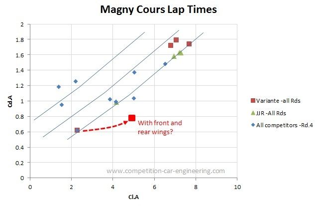
Interestingly both Variante's and JJR's cars from the high downforce rounds would have performed very similarly to their lower downforce configurations...
To my mind Variante's low downforce car would be a very good base for the final two rounds... if some nicely efficient front and rear wings are added....
Re: Khamsin Virtual Racecar Challenge 2015
Posted: 12 Sep 2015, 22:03
by cdsavage
A quick reminder for round 5: the deadline is midnight GMT at the end of the 17th (Thursday). Remember to check K1.4 and K1.5 to make sure your submission includes all the necessary files.
Re: Khamsin Virtual Racecar Challenge 2015
Posted: 13 Sep 2015, 16:16
by RicME85
Seems an ages since I submitted
Re: Khamsin Virtual Racecar Challenge 2015
Posted: 13 Sep 2015, 21:32
by machin
Unfortunately whilst Chris and I were looking at the results we noticed that the wrong engine power setting was used in the round 4 test results... So the trade-off between drag and downforce was slightly different than it should have been (i.e. slightly different from the test track)... This only changes the position of two competitors; CAEdevice and Variante's change places:
Code: Select all
                     CL.A   CD.A   COP (m)  Time (s)  Compliant
       Mantium RAY   5.02   1.03   1.567    81.416    Y
        Variante     2.29   0.62   1.614    81.952    N
         CAEdevice   6.53   1.48   1.593    82.053   N
        JJR Racing   4.15   0.99   1.699    82.142     N
      Talno Racing   3.88   1.02   1.771    82.791     Y
          Kineuton   5.04   1.37   1.609    83.028     Y
  Brook Motorsport   1.55   0.95   1.887    84.71      N
       sjns-Racing   2.21   1.25   1.579    85.385     N
Mercury Motorsport   1.40   1.18   1.234    86.096     Y
[/size]
The power setting is correct on the KVRC test track, so hopefully you've been using that to dial-in your cars, so you won't be affected. The test track is available here:
http://www.competition-car-engineering. ... KVtest.htm
Sorry for the confusion.
Re: Khamsin Virtual Racecar Challenge 2015
Posted: 13 Sep 2015, 22:04
by machin
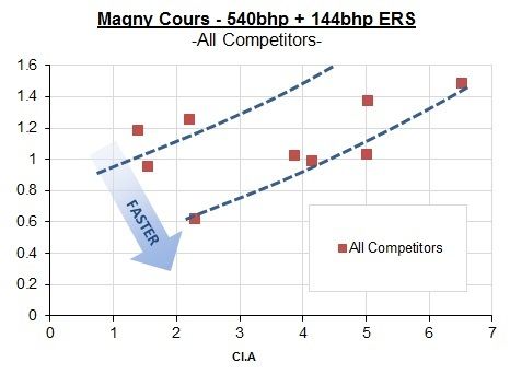
I updated the graph, but in all honesty, it doesn't really make a huge difference:-
Re: Khamsin Virtual Racecar Challenge 2015
Posted: 16 Sep 2015, 18:40
by CAEdevice
Someone could confirm the submission date/time (17/9 23.59)?
Re: Khamsin Virtual Racecar Challenge 2015
Posted: 16 Sep 2015, 22:57
by cdsavage
The deadline is midnight GMT at the end of the 17th, about 27 hours from now.
Re: Khamsin Virtual Racecar Challenge 2015
Posted: 17 Sep 2015, 22:38
by cdsavage
We have received entries from:
-Brook
-CAEdevice
-JJR Racing
-Kineuton
-Mantium
-Mercury
-TF
-Variante
The submission portal will close in about 3 hours.