Page 9 of 14
Re: F1 Cylinder Head Design and Pneumatics, a closer look
Posted: 31 Aug 2014, 20:34
by strad
Alright you math whizzes..
Is there a way to calculate the burn time at say 10 or 11 thousand rpm?
Statically you about a 1.5 to 1 rod length to stroke ratio but as rpm goes up I'm thinking it's slightly different. 1.7 or 1.3,, which way.
Re: F1 Cylinder Head Design and Pneumatics, a closer look
Posted: 18 Oct 2014, 05:04
by schmidtmotorworks
Does anyone have any thoughts on why the head was cast with the deck facing upwards?
In my experience the deck goes down and it fills from below the deck and flows into risers above the head bolts and valve guides.
Re: F1 Cylinder Head Design and Pneumatics, a closer look
Posted: 20 Jan 2015, 06:56
by hondaballs
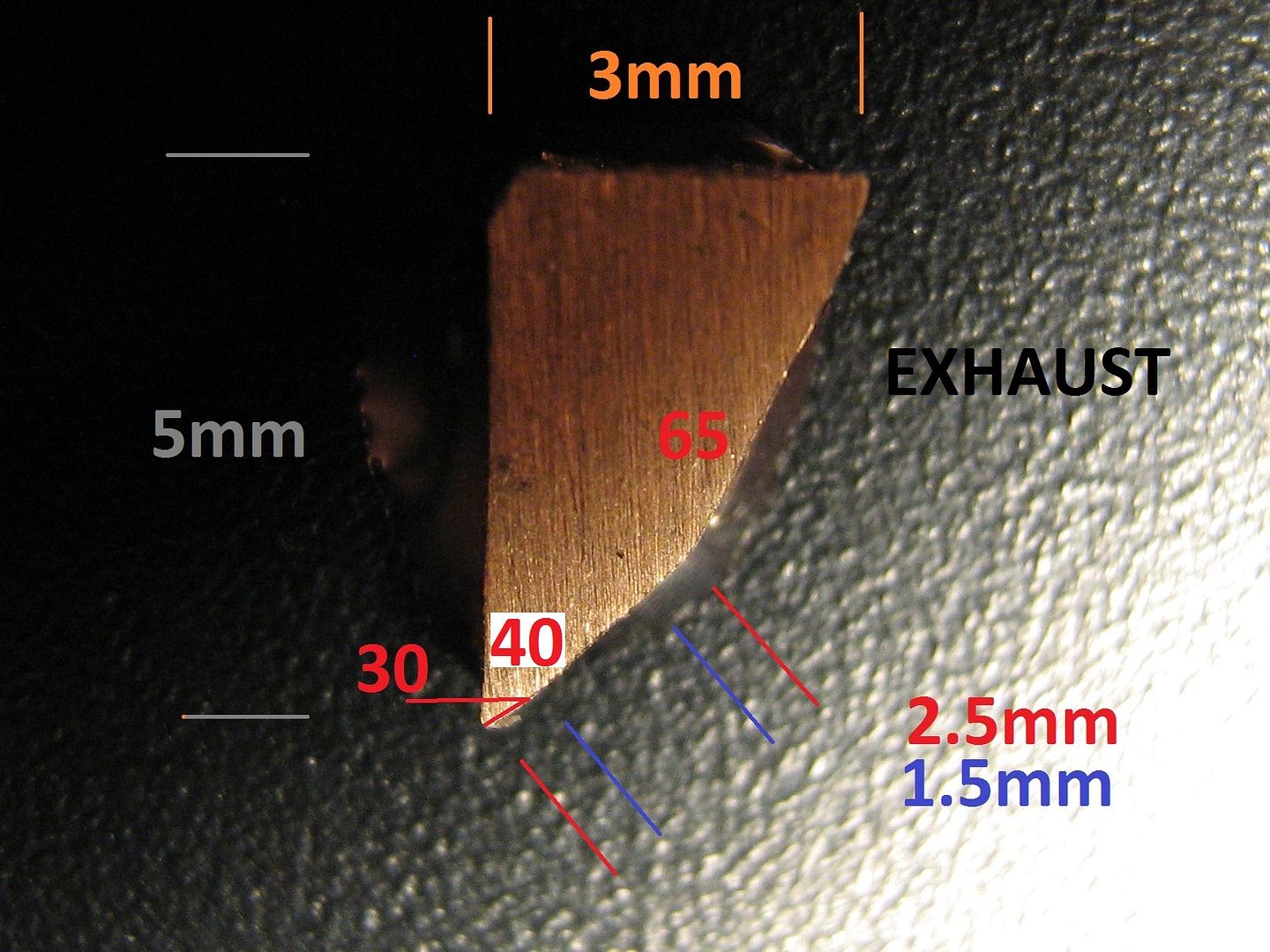
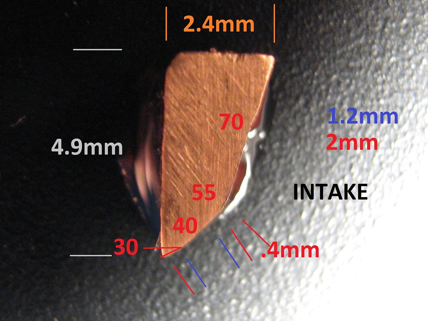
Am I seeing a 55° intake seat and 65° exhaust?
Re: F1 Cylinder Head Design and Pneumatics, a closer look
Posted: 20 Jan 2015, 11:49
by gruntguru
Both 40* I think.
Re: F1 Cylinder Head Design and Pneumatics, a closer look
Posted: 20 Jan 2015, 20:36
by hondaballs
That seems very odd if that's true.
Re: F1 Cylinder Head Design and Pneumatics, a closer look
Posted: 22 Jan 2015, 17:48
by GeoffH
Just spotted this was posted a year ago to the day, what a fast year

Since sectioned the head in two other places - will host images this evening,
Brian,
Hi Brian.
I hope you are well and just very busy with work? I saw the above post from you back in August I think?
I must admit your insight into this cylinder head is intriguing & I must compliment you on a job very well done, I find it absolutely fascinating.
Without putting any pressure on you I just wondered when we might see the next instalment?
Geoff
Re: F1 Cylinder Head Design and Pneumatics, a closer look
Posted: 25 Jan 2015, 06:14
by hondaballs
It seems to me it's 55 and 65 from this picture
Re: F1 Cylinder Head Design and Pneumatics, a closer look
Posted: 25 Jan 2015, 15:27
by GeoffH
Hi Brian.
Nice to see you are still around and that you have posted more information.
I am actually thinking of undertaking a similar project if I can get hold of a suitable donor cylinder head.
I take it you didn't just take a hacksaw to the cylinder head? I assume you used a powered saw of some type with the head held rigidly. After cutting did you do any other surface treatment like milling?
Keep up the good work, I look forward to see your future information, especially the 3D data.
Geoff
Re: F1 Cylinder Head Design and Pneumatics, a closer look
Posted: 26 Jan 2015, 00:30
by gruntguru
hondaballs wrote:It seems to me it's 55 and 65 from this picture
The "seats" are the 40 degree section in each photo. The seat width is indicated by the pair of blue dimensioning lines and the number in blue i.e. 1.5mm exhaust and 1.2mm intake.
Re: F1 Cylinder Head Design and Pneumatics, a closer look
Posted: 31 Jan 2015, 03:16
by Brian.G
GeoffH wrote:Hi Brian.
Nice to see you are still around and that you have posted more information.
I am actually thinking of undertaking a similar project if I can get hold of a suitable donor cylinder head.
I take it you didn't just take a hacksaw to the cylinder head? I assume you used a powered saw of some type with the head held rigidly. After cutting did you do any other surface treatment like milling?
Keep up the good work, I look forward to see your future information, especially the 3D data.
Geoff
Geoff,
Indeed, extremely busy with work - hope my messages cleared up cutting issues.
Will complete this thread sometime this year - when Im not sure but I will do it once I get some spare time. I never thought it would be still trending today.
Brian,
Re: F1 Cylinder Head Design and Pneumatics, a closer look
Posted: 01 Feb 2015, 07:23
by riff_raff
Looks like the seats are BeCu. It's amazing that they got those thin section seats to stay put in the cylinder head, especially the 2.4mm wall seats used on the intake side. With such a thin radial wall section the amount of interference fit you can use when installing the seats is limited. Too much interference and the thin section seat will yield.
Re: F1 Cylinder Head Design and Pneumatics, a closer look
Posted: 01 Feb 2015, 07:31
by J.A.W.
Or were the seats placed in situ & the head was then cast around them?
Re: F1 Cylinder Head Design and Pneumatics, a closer look
Posted: 01 Feb 2015, 21:11
by IVX8
Excellent engineering analysis. I am struck by the high quality of the castings, at least compared to the ones I receive from my foundry. I very much appreciate the work on the oil system, this is such a major part of the thremal management. I learned a lot. Thanks you.
Re: F1 Cylinder Head Design and Pneumatics, a closer look
Posted: 01 Feb 2015, 22:45
by Tommy Cookers
riff_raff wrote:Looks like the seats are BeCu. It's amazing that they got those thin section seats to stay put in the cylinder head, especially the 2.4mm wall seats used on the intake side. With such a thin radial wall section the amount of interference fit you can use when installing the seats is limited. Too much interference and the thin section seat will yield.
not really
call it BeCu orCuBe, it is a rather high strength material with an unusually low Elastic Modulus
so its yield strain is very high, it can be close to 10000 ppm
so has more scope in interference fitting than almost anything else ie it's very suitable for thin walls
and it has outstanding thermal conductivity of course
btw this is 2% Beryllium and very resilient (totally the opposite of high Be alloys that are banned as intolerably bad in fatigue)
Re: F1 Cylinder Head Design and Pneumatics, a closer look
Posted: 04 Feb 2015, 21:45
by Brian.G
IVX8 wrote:Excellent engineering analysis. I am struck by the high quality of the castings, at least compared to the ones I receive from my foundry. I very much appreciate the work on the oil system, this is such a major part of the thremal management. I learned a lot. Thanks you.
Thanks for taking the time to sign up and type the above - you are welcome.
The seats are indeed Beryllium Copper(Alloy 25, - 98% Cu,) and made by Delwest(name visible on interference perimeter)
Brian,