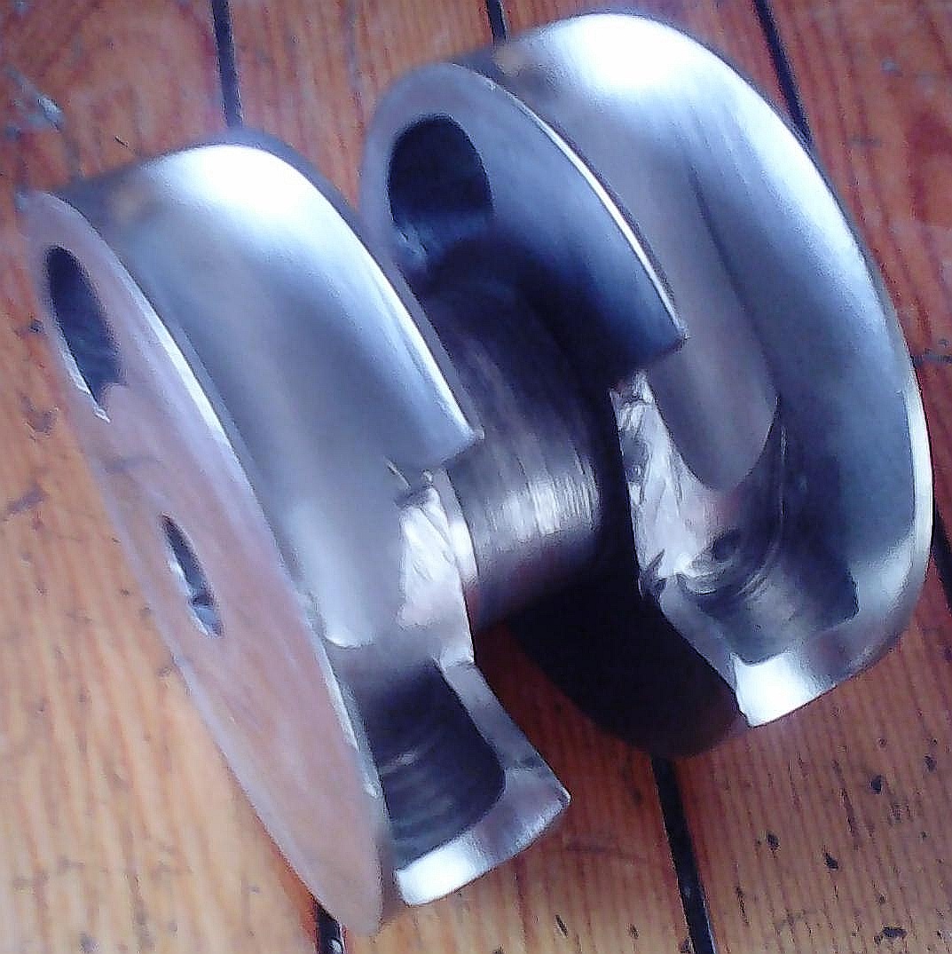
J.A.W. wrote:Here is a patent of a twin crank/rod single piston set up:
http://www.google.com/patents/US5595147
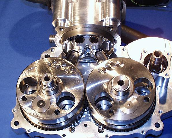
The inventor was familiar with blade & fork conrods from Harley-Davidson engines ( he did a V-triple version).
AFAIR, the rod angularity proved problematic, even when others tried rods curved like a sabre's blade.
Thanks for everything, I've looked at your spreadsheet and put in the changes, one thing i've noticed is it is effectively rotating backwards, which on a normal non offset engine being symetrical at least either side of tdc until the pistons reach half stroke, long before 90 degrees, peak speed is around 77degrees, the con rod is moving away equally in each direction of rotation. I coded to be observing the left crankshaft clockwise starting from tdc.
May be interresting is another Oz engineer Ian Drysdale created a V-twin with rods like a radial to keep cylinders inline, called the godzilla, i'll see if I can include an article I have, (he made a v8 motorbike as well, you likely already know who i'm talking about he imported a whole radial aircraft engine from the US.) Try searching for Drysdale Godzilla.
I'm just going through the motions trying to identify the ideal engine design for the Motoinno TS3 suspension, which has an amazing ability around corners, you can jump on the front brake midcorner and it holds its line, same with full throttle, handles better than a 250 gp bike and makes bumpy corners feel super smooth under brakes, also breaking load holds rear tyre to the ground not lifting the rear, rotating the bike. Likely this would have saved Marco SImoncelli given his accident was caused by the telescopic forkes oscalating on lean loosing grip and then regaining grip as the wheel mass rotated after riding up the circuit edge.
The TS3 reduces the weight, so a multi cylinders engine may not be needed if a high efficiency single could do, and more refined that single can be. So ideally a narrow light short, high efficient engine, a single cylinder Panigale taken to the logical extreme. If more power is needed a Presure wave supercharger could be used to improve efficiency.
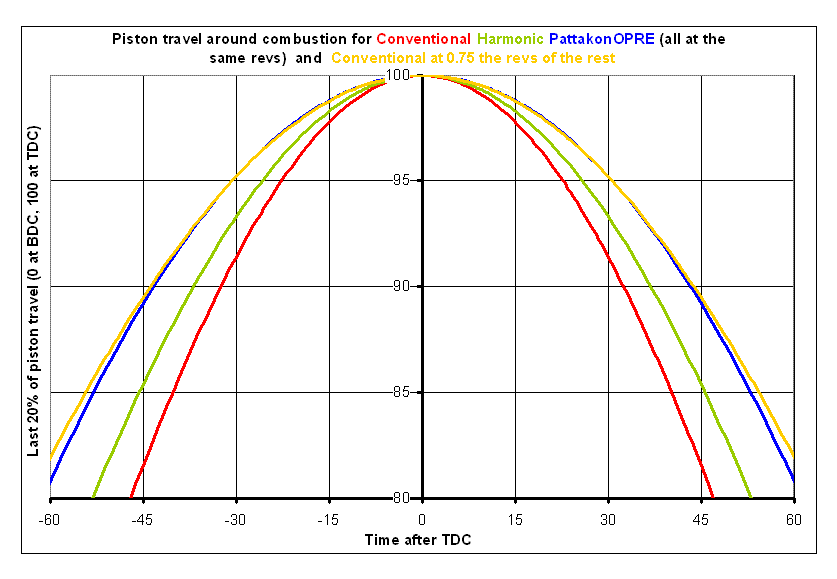
The piston motion after tdc is different where on a normal engine the big end is travelling away from cylinder centre axis shortening the rod length, whereas on the twin crank the rod is becoming more vertical, so the piston accelerates away slower rather than faster as is normal, the asymetry is now between tdc- bdc being 192 degrees and 168 back to tdc. Normally the asymetry moves from midstroke positions each side of tdc and bdc as the effective rod length changes. This effects the crank angle cylinde pressure curve and adds a few percent more rotational torque to the crank with same cylinder pressure profile. The crank/rod angle is slighly better.
Your piston speed vs bishop rotary valve seal means speed, assumption pistons have differend peak and mean speed, the brv doesn't. Total Seal say rings experience 40-50 metres/second no issues even when reversing direction and accelerating all the time so a 44 mps constant speed is fine. An 80mm valve can handle 21krpm crank speed ok. It is the bearings that can be the speed issue, An 80mm valve in a 120.65:62.3 mm bore:stroke engine can have a window of 112.65 by 36mm and the flow seems to be good on a SU2 run. Put in dual TJI units, add in lpg direct injection, and optimising the extra crank duration with multiple injections to achieve constant combustion pressure. Not having the combustion volume massive increase as the piston descends opening up the combustion chamber to the full area of the cylinder causing a massive compression ratio drop in a few degrees, given your tight compact compression volume geometry, a huge heat flux release will happen with little work done on the crank and the volume increases.
With the PatRoVa, the air streams are facing at each other, the pressure gradients between their windows will hinder each others flow into the cylinder. The are flowing almost directly into each other, this will need some carefull flow optimisation using CFD to identify the flow paths and structure and more importantly the pressure gradients. Given how accurate cfd is now, and the workflow built into SU2 for this specific optimisate task/workflow. Your geometry would be a tricky thou. (I gave it a go, but our mesh god is away now for 8 weeks I'm usually the IT guy optimising the cluster nodes). Maybe offsetting of the window positioning, staggering of the open and close times, shaping of the windows inside the cylinder, to alter their flow paths so they don't interfere with each other, maybe you can engineer in a solution like bishop did, their 'throat' to turn the air flow around and avoid flow seperations as it turned into the cylinder. A throat on the far side to the window entrance, would need the outside of the valve the far side to the window to not rotate. It's a tricky one, 3d flows are tricky effers!