Cannot be done. Rule 3.10.8: Any horizontal section between 600mm and 750mm above the reference plane, taken through bodywork located rearward of a point lying 50mm forward of the rear wheel centre line and less than 75mm from the car centre line, may contain no more than two closed symmetrical sections with a maximum total area of 5000mm2. The thickness of each section may not exceed 25mm when measured perpendicular to the car centre line. Once fully defined, the section at 745mm above the reference plane may be extruded upwards to join the sections defined in Article 3.10.1. A fillet radius no greater than 10mm may be used where these sections join
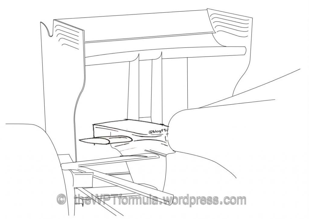
Basically you would be able to place there only two small lowered sections of the main wing. They may be helpful...but not so much if compared to Renault's solution showed in the image you posted.
Cannot be done. Rule 3.10.8: Any horizontal section between 600mm and 750mm above the reference plane, taken through bodywork located rearward of a point lying 50mm forward of the rear wheel centre line and less than 75mm from the car centre line, may contain no more than two closed symmetrical sections with a maximum total area of 5000mm2. The thickness of each section may not exceed 25mm when measured perpendicular to the car centre line. Once fully defined, the section at 745mm above the reference plane may be extruded upwards to join the sections defined in Article 3.10.1. A fillet radius no greater than 10mm may be used where these sections join
Basically you would be able to place there only two small lowered sections of the main wing. They may be helpful...but not so much if compared to Renault's solution showed in the image you posted.
The rule describes the wing supports, not the wing itself.
There can be no dips in the wing section, like those shown, unless most of the wing section doesn't go to the minimum height
Why cant there be any dips??
Re: 2014 Design
Posted: 19 Jan 2014, 02:45
by variante
wuzak wrote:The rule describes the wing supports, not the wing itself.
Nope: it describes generic bodywork. In FIA's minds that bodywork is supposed to be "wing supports", but in designer's minds there may be something else.
BTW There can be dips. You can only argue that the pic i showed earlier is not the most accurate... and in fact it is not supposed to be perfectly accurate...
Re: 2014 Design
Posted: 19 Jan 2014, 02:52
by wuzak
When I say no dips, I men they can only fall in the box that defines the rear wing elements. That is between 750mm and 950mm above the reference plane.
There can be a dip in the leading edge, but that cannot go the whole chord of the wing.
3.10 Bodywork behind the rear wheel centre line :
3.10.1 Other than the bodywork defined in Article 3.10.9, any bodywork behind a point lying 50mm forward of the rear wheel centre line which is more than 750mm above the reference plane, and less than 355mm from the car centre line, must lie in an area when viewed from the side of the car that is situated between the rear wheel centre line and a point 350mm behind it.
With the exception of minimal parts solely associated with adjustment of the section in accordance with Article 3.18 :
a) When viewed from the side of the car, no longitudinal vertical cross section may have more than two sections in this area, each of which must be closed.
b) No part of these longitudinal vertical cross sections in contact with the external air stream may have a local concave radius of curvature smaller than 100mm.
Once the rearmost and uppermost section is defined, ‘gurney’ type trim tabs may be fitted to the trailing edge. When measured in any longitudinal vertical cross section no dimension of any such trim tab may exceed 20mm.
The chord of the rearmost and uppermost closed section must always be smaller than the chord of the lowermost section at the same lateral station.
Furthermore, the distance between adjacent sections at any longitudinal vertical plane must lie between 10mm and 15mm at their closest position, except, in accordance with Article 3.18, when this distance must lie between 10mm and 65mm.
Re: 2014 Design
Posted: 19 Jan 2014, 02:58
by wuzak
variante wrote:
wuzak wrote:The rule describes the wing supports, not the wing itself.
Nope: it describes generic bodywork. In FIA's minds that bodywork is supposed to be "wing supports", but in designer's minds there may be something else.
BTW There can be dips. You can only argue that the pic i showed earlier is not the most accurate... and in fact it is not supposed to be perfectly accurate...
3.10.8 Any horizontal section between 600mm and 750mm above the reference plane, taken through bodywork located rearward of a point lying 50mm forward of the rear wheel centre line and less than 75mm from the car centre line, may contain no more than two closed symmetrical sections with a maximum total area of 5000mm2. The thickness of each section may not exceed 25mm when measured perpendicular to the car centre line. Once fully defined, the section at 745mm above the reference plane may be extruded upwards to join the sections defined in Article 3.10.2. A fillet radius no greater than 10mm may be used where these sections join.
The sections defined are horizontal (parallel to the reference plane). They must be closed symmetrical sections and are defined below the wing section box. They then can be extruded upwards to meet the wing, with no more than a 10mm radius at the intersection.
Re: 2014 Design
Posted: 19 Jan 2014, 03:10
by variante
yes, that's right: the part you underlined tells us what i was trying to show, which is: there is space for the main wing to be "extruded", but that space is awfully small and over regulated to produce an actual gain in performance.
Re: 2014 Design
Posted: 19 Jan 2014, 03:27
by Holm86
But is there no exclusion zone in the 150mm central section anymore?? On the last page someone mentioned that this zone has been changed to 200 mm now.
Re: 2014 Design
Posted: 19 Jan 2014, 03:40
by PlatinumZealot
It seems so. The fillet radius of 10mm, and the that the shape has to be an extrusion makes it pretty limited what you can shape in that area.
Re: 2014 Design
Posted: 19 Jan 2014, 03:48
by variante
Holm86 wrote:But is there no exclusion zone in the 150mm central section anymore?? On the last page someone mentioned that this zone has been changed to 200 mm now.
yes, there is a 200mm wide "free zone", which however is partially in contrast with article 3.10.8. This arcticle talks about a 150mm wide zone, so you only have -by subtraction- a 50mm wide zone which is actually "regulations free"; to be more exact, this area is split in 2 parts, each 25mm wide: one goes from 75 to 100mm from the car centre line, while the other one is just the very same area placed on the opposite side of the car, simmetrically.
The extruded sections of the CAD i showed earlier do end in the 200mm wide free area.
Re: 2014 Design
Posted: 19 Jan 2014, 04:15
by wuzak
Holm86 wrote:But is there no exclusion zone in the 150mm central section anymore?? On the last page someone mentioned that this zone has been changed to 200 mm now.
The exclusion zone is lower, in the area of the monkey seat.
Note that the wing supports must be less than 75mm from the centreline from 600mm to 750mm above the reference plane.
Re: 2014 Design
Posted: 19 Jan 2014, 04:19
by wuzak
variante wrote:yes, that's right: the part you underlined tells us what i was trying to show, which is: there is space for the main wing to be "extruded", but that space is awfully small and over regulated to produce an actual gain in performance.
It can't be extruded in the wing.
Only the profile of the supports can be extruded to meet the wing.
Re: 2014 Design
Posted: 19 Jan 2014, 13:12
by hollus
On the rear wing regulations, what is the point of the part in normal font? Why specify a large element in the lower front and a smaller element above and trailing? What's the point? Would it be more efficient to have it the other way around or in any other arrangement? Sounds like unnecessary constraints.
Maybe this is a new regulation dating only from the introduction of DRS?
wuzak wrote:
3.10 Bodywork behind the rear wheel centre line :
3.10.1 Other than the bodywork defined in Article 3.10.9, any bodywork behind a point lying 50mm forward of the rear wheel centre line which is more than 750mm above the reference plane, and less than 355mm from the car centre line, must lie in an area when viewed from the side of the car that is situated between the rear wheel centre line and a point 350mm behind it.
With the exception of minimal parts solely associated with adjustment of the section in accordance with Article 3.18 :
a) When viewed from the side of the car, no longitudinal vertical cross section may have more than two sections in this area, each of which must be closed.
b) No part of these longitudinal vertical cross sections in contact with the external air stream may have a local concave radius of curvature smaller than 100mm.
Once the rearmost and uppermost section is defined, ‘gurney’ type trim tabs may be fitted to the trailing edge. When measured in any longitudinal vertical cross section no dimension of any such trim tab may exceed 20mm.
The chord of the rearmost and uppermost closed section must always be smaller than the chord of the lowermost section at the same lateral station. Furthermore, the distance between adjacent sections at any longitudinal vertical plane must lie between 10mm and 15mm at their closest position, except, in accordance with Article 3.18, when this distance must lie between 10mm and 65mm.
Re: 2014 Design
Posted: 19 Jan 2014, 18:35
by FW17
Since he gear box casing can be shaped however required can it form part of part of a beam wing and the rest be the camera pod?
1.4 Bodywork :
All entirely sprung parts of the car in contact with the external air stream, except cameras,
camera housings and the parts definitely associated with the mechanical functioning of the
engine, transmission and running gear. Airboxes, radiators and engine exhausts are considered
to be part of the bodywork.