Page 16 of 19
Re: Ringo F1 design
Posted: 12 Feb 2012, 11:16
by Ferrari_Ivan
Tozza Mazza wrote:Ferrari_Ivan wrote:are there hidden innovative aerodynamic points?
Oh god...
why?
my English sucks?
Re: Ringo F1 design
Posted: 12 Feb 2012, 11:27
by Tozza Mazza
Ferrari_Ivan wrote:Tozza Mazza wrote:Ferrari_Ivan wrote:are there hidden innovative aerodynamic points?
Oh god...
why?
my English sucks?
Behold the ellipse, and the super secret red bull sidepod...
Re: Ringo F1 design
Posted: 12 Feb 2012, 13:03
by Ferrari_Ivan
ok! I asked this because when I think of design or an innovative idea, many details are not seen by others. I like the details. I love the details.
Re: Ringo F1 design
Posted: 12 Feb 2012, 13:56
by wesley123
It wasnt to tease you Ivan, read the Red Bull RB7 topic and it will all become clear
Re: Ringo F1 design
Posted: 12 Feb 2012, 21:59
by Ferrari_Ivan
wesley123 wrote:It wasnt to tease you Ivan, read the Red Bull RB7 topic and it will all become clear

I'm sorry. I did not understand very well. for me to write and read English is complicated. I'm not very good with this language. if you see some very big mistake tell me! thanks

Re: Ringo F1 design
Posted: 13 Feb 2012, 06:40
by ringo
MemroableC wrote:Ringo if you get a chance could you upload the car, as a fellow solidworks user i would love to see the technique used to model the car and maybe run some cfd on it for fun.
I'm finishing up. I have done some work on the floor this weekend.
The technique is pretty much lofts and solid modeling. All that is required is a bit of discipline and patience with the sketches. The relations are very importance, especially tangency relations.
As for the ellipse it's not really the secret. Let's see how redbull do first.
I'm a little apprehensive of handing out the model but i'll show what i do on here when it's done.
Re: Ringo F1 design
Posted: 13 Feb 2012, 06:43
by ringo
bhallg2k wrote:I have the strangest feeling that someone around here is responsible for this.

Ahh

Well well. That is kinda taking it too far.
but hey...

just cant get enough!
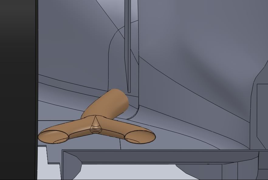
how about these wings though:

it's not by chance.
Re: Ringo F1 design
Posted: 13 Feb 2012, 08:13
by MIKEY_!
???

I can't see any wings on that tow truck
Re: Ringo F1 design
Posted: 18 Feb 2012, 18:00
by ringo
i have a question.
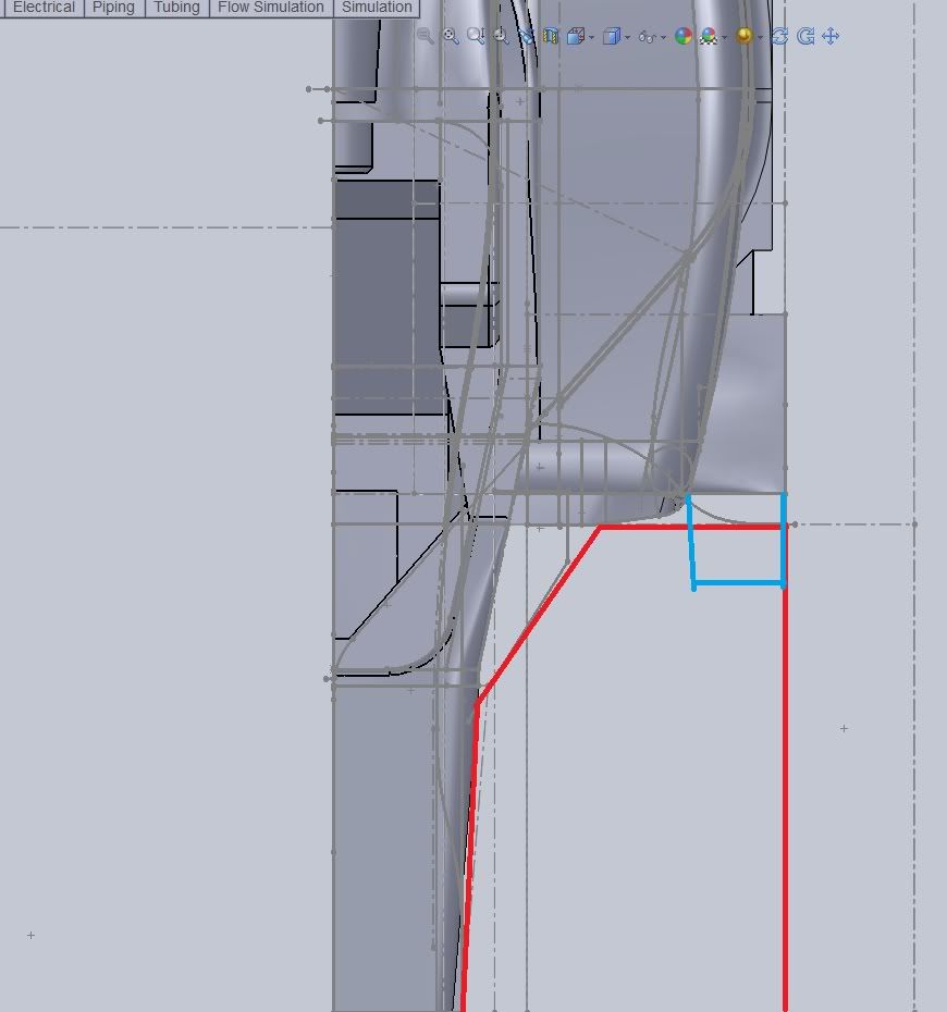
For the turning vanes, how far out can i put them?
The rulese say there should be no body work in the red area. I think there is an exception for mirrors.
The thing is, turning vanes aren't mirros, so can the foot plate for the turning vane be situated in the red area (blue lines represent turning vane foot plate) or should i stay outside of the red?
Re: Ringo F1 design
Posted: 18 Feb 2012, 18:30
by jordangp
I'd stay completely out the red area if I were you
Re: Ringo F1 design
Posted: 18 Feb 2012, 18:33
by Tozza Mazza
ringo wrote:i have a question.
For the turning vanes, how far out can i put them?
The rulese say there should be no body work in the red area. I think there is an exception for mirrors.
The thing is, turning vanes aren't mirros, so can the foot plate for the turning vane be situated in the red area (blue lines represent turning vane foot plate) or should i stay outside of the red?
IIRC the area for them starts at 450mm ahead of the cockpit entry template.
Re: Ringo F1 design
Posted: 18 Feb 2012, 23:16
by Pierce89
bhallg2k wrote:I have the strangest feeling that someone around here is responsible for this.
I take it you're referring to someone's trumpeting of the ellipse's benefits in spanwise loading leading to reduced vortex generation
Re: Ringo F1 design
Posted: 19 Feb 2012, 21:38
by machin
ringo wrote:i have a question.
For the turning vanes, how far out can i put them?
The rulese say there should be no body work in the red area. I think there is an exception for mirrors.
The thing is, turning vanes aren't mirros, so can the foot plate for the turning vane be situated in the red area (blue lines represent turning vane foot plate) or should i stay outside of the red?
I agree with JordanGP; keep out of the red zone... if you look at the real cars they generally position the leading edge of their radiator intakes right at the back of the zone which doesn't need to meet the minimum radius rule, that means they maximise the space available for turning vanes and flow conditioners infront of the sidepods...
Re: Ringo F1 design
Posted: 19 Feb 2012, 22:05
by ringo
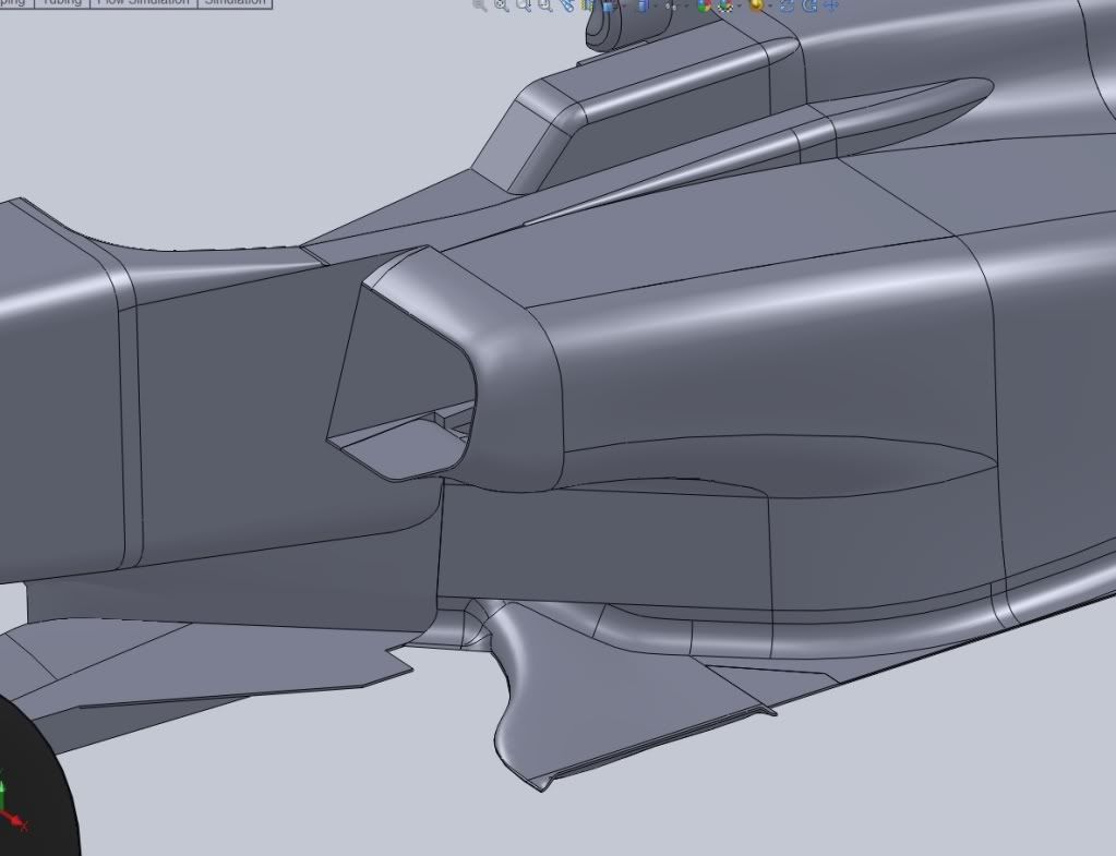
Yes,
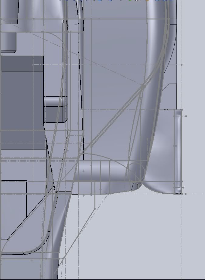
my sidepods are different. The lower lip extends to the red line, while the upper lip is back more. I steal some downforce this way with the lip extension airfoil shaped.
So i guess i'll keep the turning vane where i intended. You can see that curve right at the floors edge meeting the red line and running back to the chassis.
Re: Ringo F1 design
Posted: 22 Feb 2012, 07:25
by ringo
gonna move on now to the gear box end of things and beam wing. Sorry for the snail pace.