Page 3 of 4
Re: Suspension kinematics detail design challenges
Posted: 01 Nov 2010, 13:27
by autogyro
How about plain bearings, pressure fed with fluid from damper reservoir?
Re: Suspension kinematics detail design challenges
Posted: 01 Nov 2010, 17:16
by Belatti
Nice idea, but I would say at first glance that its more complex, expensive and has an extra factor against reliability.
Re: Suspension kinematics detail design challenges
Posted: 06 Nov 2010, 05:32
by riff_raff
autogyro wrote:How about plain bearings, pressure fed with fluid from damper reservoir?
autogyro,
The pivot bearings in suspension components are only subject to oscillatory motions. Thus they operate primarily in boundary contact conditions. Unless the oil pressure feed was sufficiently high (ie. several thousand psi) to achieve a hydrostatic contact condition, then it would not be of benefit.
Regards,
riff_raff
Re: Suspension kinematics detail design challenges
Posted: 06 Nov 2010, 13:26
by autogyro
I realised that riff_raff
A sealed system at 3000psi should be possible.
Work safety? Damn.
Re: Suspension kinematics detail design challenges
Posted: 19 Feb 2011, 19:47
by mep
Ok time to bring this topic up again. It was supposed to be something like a melting pot of suspension design.
I got some pictures of the Lunar Roving Vehicle and though some of you guys might be interested in it.
Interesting in the design is that it has 4 electric motors located inside the wheels. Notice that the designers added some additional tube to connect the motors with the chassis to transfer the torque. Obviously they did not like it to be transferred trough the wishbones.


It is claimed that each of the electric motors had a power of 0,18 kW. This gives the vehicle a total power of 0,72 kW (around 1 PS). That really is not very much. Considering you drive off-road on dusty surface I am surprised this even is possible. For sure it is not a race car
Re: Suspension kinematics detail design challenges
Posted: 20 Feb 2011, 07:48
by riff_raff
mep,
Those pictures are likely of a terrestrial test vehicle. The actual lunar rover had tires made of metal screen mesh, and were not pneumatic. The extremely low temperatures on the lunar surface and during space flight would have caused failure in a rubber tire.

As for that "torque tube", I believe that was a strut used to deploy the suspension. The lunar rover was basically folded up to fit inside a small space on the lunar lander. The suspension arms and wheels were folded over the chassis during storage.

Re: Suspension kinematics detail design challenges
Posted: 20 Feb 2011, 10:27
by Jersey Tom
Those lunar tires are Goodyears, I'll add

Re: Suspension kinematics detail design challenges
Posted: 20 Feb 2011, 10:56
by Tim.Wright
[warning not a single serious point in the following post]
The geometry of the double wishbone suspension is actuatlly not a bad start for a race suspension

Some camber gain in bump already built in.
I like the look of the bent fittings on the inboard end of the arms. When I first looked at it I thought it was a failed rod end. Looks like they took the idea of a rod end in bending a little too extreme.
For sure it wouldn't have won any intergalactic 1/4 mile races.
Tim
Re: Suspension kinematics detail design challenges
Posted: 20 Feb 2011, 12:32
by mep
I think I have to add that I took those pictures myself and yes I was not on the moon lately.
I don’t know what kind of car it is for sure not one of the original ones. I guess it is just a replica. If it is a replica then I expect it to be from the moon vehicle. Making a replica of a terrestrial vehicle makes little sense to me. Or do you think it looks strong enough to drive on earth with a total mass of 700kg?
However we have already found that the tires are not correct.
Why do they not sink into the dusty surface of the moon?
Is those dust that solid that you can drive on it just with steel net?
riff_raff wrote:As for that "torque tube", I believe that was a strut used to deploy the suspension. The lunar rover was basically folded up to fit inside a small space on the lunar lander. The suspension arms and wheels were folded over the chassis during storage.
Doesn’t really explain why you need that tube. Even if you use it to fix the suspension in the folded position you could remove it when you build up the car. Compared to the wishbone tubes this one looks quite big in diameter. The explanation to transmit torque makes more sense in my opinion.
We should also not forget that the guys wear really fat gloves when they have to assemble the car. I wonder if they even can handle some of the small parts we see in the picture.
Have you also noticed the steering mechanism?
There is a groove on the chassis. Looks a bit like its moving fore and back but this could in fact also be there to fold the car together. I haven’t really figured out yet how the steering works.
I think I have to mention again it has just 0,72kW.
Ca. 1 PS
Ca. 1HP
Any comments?
Re: Suspension kinematics detail design challenges
Posted: 21 Feb 2011, 13:42
by Onch
I think the tubes are indeed meant to deploy the suspension, with 0.18kW per wheel the wishbones should be more than up to the job...
The low power should be sufficient thanks to much lower gravity on the moon, that means less friction forces and less force required to go up a hill. That thing does anyway not need to move extremely fast (that is, unless it encounters bad mooded aliens, but that proved not be have been the case!

).
As for the steering it is indeed proably a bit trick in order to allow the folding of the suspension for the travel.
It looks like the ball joint kinematic is defined by a hinge attached to the chassis (far right on the picture). The slot allows the rack (?) to move back and forth as steering is applied.
All in all a very nice example of 'form follows function'...!
Re: Suspension kinematics detail design challenges
Posted: 23 Feb 2011, 08:33
by riff_raff
Consider this: On the lunar surface, the rover's aero drag was essentially zero. Perfect aerodynamics.
Re: Suspension kinematics detail design challenges
Posted: 24 Feb 2011, 00:10
by mep
I expected those to arguments to pop up and yea finally they are here. My comments never seem to attract much attention.
1. lower gravity
2. no air resistance
Agreed those points are very valid. However the mass of the vehicle remains at 700kg so at least acceleration is affected by this. The car has no drag so how is top speed even limited? Is there any other force which is velocity dependant apart from drag? The electric motors will have a max rpm. Well what is even limiting the rpm of an electric motor? The change of the electric field? I expect the max speed of a rocket is limited by the speed of the exhaust gases.
Well lets come back to the rover which is moving on dust. What do you think how much energy is consumed to move trough that dust? There is no water so possible nothing holds the particles together. Those tires made of a steel web might just cut trough it consuming the power.
Re: Suspension kinematics detail design challenges
Posted: 24 Feb 2011, 00:27
by Tim.Wright
The motor torque vs speed diagram will show a drop of speed at high RPM. When the torque drops to the level which equals your friction, then it stops accelerating.
Also, coulumb friction is not completely independant of speed.
tim
Re: Suspension kinematics detail design challenges
Posted: 24 Feb 2011, 01:58
by Ciro Pabón
mep wrote:I expected those to arguments to pop up and yea finally they are here. My comments never seem to attract much attention.
1. lower gravity
2. no air resistance
Agreed those points are very valid. However the mass of the vehicle remains at 700kg so at least acceleration is affected by this...
Sure,
you have to design a suspension for 1/6th of gravity, so the elements that resist vertical loads can be very thin, compared with ones made for the Earth.
However the inertia is the same. So all elements that resist forces in the horizontal direction have to be reinforced, compared with those that resist vertical forces that can be made lighter.
I understand it is quite difficult to learn to jump in the moon: while you feel lighter when you jump
up, you are as heavy as always when you try to stop moving
ahead.
mep wrote:Well lets come back to the rover which is moving on dust. What do you think how much energy is consumed to move trough that dust? There is no water so possible nothing holds the particles together. Those tires made of a steel web might just cut trough it consuming the power.
Well, fine particles are held in place by electric charges. In dust, the electric charges migrate to the pointy parts which become positive (that's why lighting rods are more or less pointy), while the flat parts are negative. I won't delve into double layers, isomorph substitutions nor free hydroxil ions... but all contribute to this electric potential.
So, you do not need water for clays to develop cohesion: they do it by electricity.
On the left, wet dust, on the right, dry dust. In both systems, you have flat particles, and pointy parts of them stick to flat parts of others, edge to face.

That's why the darned dust is so hard to clean from a dirty suit, it adheres by electricity. Soap breaks those electrical bonds.
So, by this cohesion the tyre cannot penetrate the dust. Even when you don't have suction from water (by capillary action) you have electricity in dry particles that gives you cohesion.
Now, this cohesion resist penetration in areas much larger than the size of grains, because arches are formed.
Catenary sand arch, internal forces are mainly compression, there little torque or tension, so it can be made of sand.

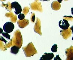
Lunar soil is made of very round particles (for a soil) because most of them are not created by thermal expansion or hydration, as in Earth, but by meteorite collisions. Nonetheless, in a picture of the lunar soil there are a few flat flakes here and there. Like this:
Lunar soil
BTW, mep, I'm always interested by your posts.
Re: Suspension kinematics detail design challenges
Posted: 25 Feb 2011, 00:47
by mep
Ciro Pabón wrote:
BTW, mep, I'm always interested by your posts.
Thanks Ciro, sometimes I need acknowledgement like this because I feel frustrated when I hardly get responses meanwhile other topics easily get 70 pages and more without delivering much information. I guess you know those kind of feelings.
I found a interesting paper about the rover. I just fly over it but it seems like some of the mysteries can be solved by it. The torque rod actually is the damper. Seems like the model I took pictures of has many mistakes like the wheels, missing rear wheel steering and maybe a wrong damper angle. Apologies for that.
http://www.hq.nasa.gov/alsj/LRV_OpsNAS8-25145.pdf


