Page 5 of 19
Re: Ringo F1 design
Posted: 19 Jun 2011, 17:30
by flyboy2160
"....The flow is weakest midspan on a vertical wing like an F1 wing. Strongest flow is adjacent to the end plates...."
r man,
why so? do you have a cfd of this?
flyboy
Re: Ringo F1 design
Posted: 19 Jun 2011, 17:52
by ringo
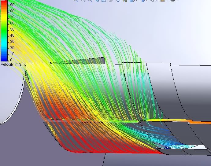
This is a different wing from the f duct discussion days. But it demonstrates the air speeds across the wing well.
Re: Ringo F1 design
Posted: 19 Jun 2011, 17:57
by ringo
marcush. wrote:that rear wing flap idea is cool but couldn´t it be exploited even more agressively,redirecting flows and shedding even more drag?
It's possible though the limitation is that the main plane has to be bigger than the flap. The biggest i can go with the flap is < 50% main plane in a strict sense.
Re: Ringo F1 design
Posted: 19 Jun 2011, 19:01
by hardingfv32
"The flow is weakest midspan on a vertical wing like an F1 wing."
Is this a quality of the wing itself or is the wing seeing a non-uniform flow in front of it?
Brian
Re: Ringo F1 design
Posted: 20 Jun 2011, 01:07
by ringo
It's a quality of the wing.
The flow stays more attached at the end plate on a wing of such high camber.
Even with uniform flow at the front, it will still result with stronger up wash at the ends.
The Renault shaped wing and the Williams shaped wing in Canada demonstrates attempts to compensate for this phenomena as well. So do wings of the past years with slots in the middle.
Re: Ringo F1 design
Posted: 20 Jun 2011, 01:34
by flyboy2160

maybe i need to have more beer, because i can't see how you can get 0 velocity airflow at the lower middle section (assuming i'm looking at your plot correctly - but maybe that's another beer deficiency!
)
edit: ok, after another brew, i realized that the cfd view is looking forward and up at the bottom of the wing sections from behind the wing...right? or shall i go for another draft?
if my new idea of the cfd view is correct, then, yes, it makes sense that the center will separate more than the areas near the endplates (this is the same thing with the diffuser "channels.") i think i'll have another to celebrate my figuring out the cfd view!
edit again: we need a beer drinking smilie
Re: Ringo F1 design
Posted: 20 Jun 2011, 01:54
by ringo
It's not zero.
But it's close to it.
zero is the darkest blue. Dark blue can also mean negative.
Your asking the air to climb up a wall, purely on suction basically. It shouldn't be surprising that it can lose energy trying to "climb" the back of that wing.

Looking at this ferrari wing, you can see the attempts to energize the flow in the middle.
Near the endplates there is less concern for stalling.
Here it is again, look at the flow near to the end plates compared to the middle where the flovis hardly moves.

Re: Ringo F1 design
Posted: 20 Jun 2011, 01:55
by flyboy2160
do the current regulations prohibit the equivalent of a third "endplate" in the center of the wing, thus replicating the improvements in separation achieved by using channeled diffusers?
Re: Ringo F1 design
Posted: 20 Jun 2011, 02:09
by ringo
I don't think it's prohibited.
It can go there and work well, but in yaw condition one half of the wing will be starved of air.
Maybe if it's placed more to the back it wont have any ill effect in yaw.

Re: Ringo F1 design
Posted: 20 Jun 2011, 08:00
by Robbobnob
so the the Shark fin that Red Bull ran was more to do with the energizing of the flow on the wing element?
I was under the assumption that the shark fin was employed to straighten the airflow and eliminate any pressure drag caused by the shadow of the roll hoop and intake.
Interestingly also increasing yaw efficiency??
http://www.f1technical.net/development/228
Re: Ringo F1 design
Posted: 20 Jun 2011, 08:23
by Robbobnob
also how are you going to determine the cooling requirements, by simulation or by designers judgement?
Re: Ringo F1 design
Posted: 20 Jun 2011, 14:53
by flyboy2160
ringo wrote:I don't think it's prohibited.
It can go there and work well, but in yaw condition one half of the wing will be starved of air.
Maybe if it's placed more to the back it wont have any ill effect in yaw.
but how high can the yaw angle really be?
one of the endplates is already giving this yaw blockage.
you're not going to make me fire up my own new cfd seat are you?
Re: Ringo F1 design
Posted: 20 Jun 2011, 15:18
by ringo
Robbobnob wrote:so the the Shark fin that Red Bull ran was more to do with the energizing of the flow on the wing element?
I was under the assumption that the shark fin was employed to straighten the airflow and eliminate any pressure drag caused by the shadow of the roll hoop and intake.
Interestingly also increasing yaw efficiency??
http://www.f1technical.net/development/228
It's not energizing it, it's just preventing it from wasting energy.
I am more concerned with the back of the wing. A little shark fin there is what i am pondering.
The yaw efficiency is better without the shark fin. Or with a moderate shark fin. It must not screen the wing
Re: Ringo F1 design
Posted: 20 Jun 2011, 15:28
by Giblet
Interesting wing design Ringo. Unique and interesting thinking within the new regulations and the scope of DRS.
Re: Ringo F1 design
Posted: 20 Jun 2011, 16:17
by ringo
Robbobnob wrote:also how are you going to determine the cooling requirements, by simulation or by designers judgement?
Some thermodynamic calculations, then heat exchanger design. I can put a sample calculation when the time comes. That will be the heat rejection requirement for the radiator, but it will be difficult to actually estimate how to get that requirement passing through the body of the car.
I would have to brush up on my heat and mass transport before i do that.
The benefits, i suppose is the responsiveness to re attachment and the middle ground between DRS top speed gains.
We'll see.