Page 7 of 8
Re: Idea for V6 turbo configuration
Posted: 29 Jan 2012, 19:59
by flynfrog
noname wrote:WhiteBlue wrote:Not any more. The advanced manufacturers of small axial turbines do the whole wheel out of one solid piece with 5-axis cutting.
You can have fully machined turbine wheel but, to my knowledge, the process is being used mainly to make TiAL wheels (or lower temp. applications). And ceramic materials are banned (except stuff like bearings).
Materials used for high temp wheels (they will, I think, work above 1000degC) exist only as casting. They are machined (contour, back side, etc.), but they are not made from the billet. However wax patterns are made on 5 axis CNCs.
Compressor wheels, on the other hand, are fully machined.
You can still machine High nickle alloys in a single piece system.
single piece wheels are generally done when turbines become to small to easily cast and a assemble its mostly for weight savings and manufactuability.
in smaller applications the centrifugal compressor is used to cut down rotating mass of multiple stages. As size goes up the inefficiencies start to climb and the weight savings advantage is lost. There is still the packaging benefit that might be worth more then we think in a cramped f1 car.
Re: Idea for V6 turbo configuration
Posted: 29 Jan 2012, 20:47
by pgfpro
neilbah wrote:ok to settle the argument we'll use a mixed-flow compressor or 'diagonal flow' one which is a combination of the axial and radial compressors
Could they add a axial turbine or make it part of the radial turbine?
Example: In my picture of my BW S400SX4-75mm where the Sharpie pen is set on top of the turbine this would be the shaft of the axial turbine?
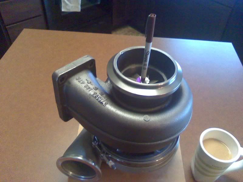
This way they could utilize the pressure ratios of a radial design to control turbine wheel speed for convential turbo engine power, and still have the advantages of the axial turbine for exhaust energy recovery.
Rules wise they could make it one unit. A good example is how BW "EFR" turbos now have their new "high flow internal gates" and "BCSV Boost Control solenoid Valve" all incorporated into one unit.
Re: Idea for V6 turbo configuration
Posted: 29 Jan 2012, 21:56
by neilbah
i think the system would use vanes that could change angles, as the turbo spools and accelerates,different stages kick in, but as for the specifics i dont have a clue, i only just learnt about their existence from inspiration to look them up in google after reading this thread, one would argue that its not worth using in the automobile market, although theres been plenty of research its probably not viable against cost for the gains. At least not until now, where we see commercial applications of compound charging and car manufacturers embracing the turbocharger again, such as VW, it might be one of the reasons they are keen to enter F1, I havent looked into what patents they have..
Re: Idea for V6 turbo configuration
Posted: 30 Jan 2012, 07:11
by WhiteBlue
neilbah wrote:i think the system would use vanes that could change angles, as the turbo spools and accelerates,different stages kick in...
Multiple stages and variable geometries are currently prohibited by the 2014 tech regulations.
Re: Idea for V6 turbo configuration
Posted: 30 Jan 2012, 08:30
by mx_tifoso
WB, what's the reasoning behind that? Just another rule to prevent excessive power/speed?
Re: Idea for V6 turbo configuration
Posted: 30 Jan 2012, 09:53
by WhiteBlue
mx_tifoso wrote:WB, what's the reasoning behind that? Just another rule to prevent excessive power/speed?
AFAIK the restrictions were put in place to limit initial development cost. Cosworth belongs to the engine suppliers and they are not going to have deep pockets. I guess they simply left those refinements for later when the initial costs for developing the engine have been amortized.
Excessive power/speed would be better reigned in by further fuel cuts.
Re: Idea for V6 turbo configuration
Posted: 04 Feb 2012, 19:31
by autogyro
WhiteBlue wrote:mx_tifoso wrote:WB, what's the reasoning behind that? Just another rule to prevent excessive power/speed?
AFAIK the restrictions were put in place to limit initial development cost. Cosworth belongs to the engine suppliers and they are not going to have deep pockets. I guess they simply left those refinements for later when the initial costs for developing the engine have been amortized.
Excessive power/speed would be better reigned in by further fuel cuts.
I agree on the last but if the FIA is to regulate so tightly the outline for boost and Hers/Kers why doesn't it just design the whole thing itself?
Re: Idea for V6 turbo configuration
Posted: 08 Feb 2012, 23:18
by Edis
flynfrog wrote:noname wrote:WhiteBlue wrote:Not any more. The advanced manufacturers of small axial turbines do the whole wheel out of one solid piece with 5-axis cutting.
You can have fully machined turbine wheel but, to my knowledge, the process is being used mainly to make TiAL wheels (or lower temp. applications). And ceramic materials are banned (except stuff like bearings).
Materials used for high temp wheels (they will, I think, work above 1000degC) exist only as casting. They are machined (contour, back side, etc.), but they are not made from the billet. However wax patterns are made on 5 axis CNCs.
Compressor wheels, on the other hand, are fully machined.
You can still machine High nickle alloys in a single piece system.
single piece wheels are generally done when turbines become to small to easily cast and a assemble its mostly for weight savings and manufactuability.
in smaller applications the centrifugal compressor is used to cut down rotating mass of multiple stages. As size goes up the inefficiencies start to climb and the weight savings advantage is lost. There is still the packaging benefit that might be worth more then we think in a cramped f1 car.
Single piece wheels are commonly known as blisks (bladed disk), but if we're talking about turbines they are cast using directional solidification for optimum grain structure.
Re: Idea for V6 turbo configuration
Posted: 07 Mar 2012, 16:59
by Muskrat
Are the new 1.6 V6 Turbos 1 or 2 turbo lumps - was hoping 2 one hanging off each side ala most of te 80s ones.
Re: Idea for V6 turbo configuration
Posted: 08 Mar 2012, 20:22
by Edis
Muskrat wrote:Are the new 1.6 V6 Turbos 1 or 2 turbo lumps - was hoping 2 one hanging off each side ala most of te 80s ones.
A single turbo behind the engine.
Re: Idea for V6 turbo configuration
Posted: 08 Mar 2012, 20:57
by WhiteBlue
The single turbo is partly specified for sound reasons but also for simplicity and cost. If you think about it it would make the design of the MGUH much more complicated if you were to use two units. Everything from the power electronics to the rotor and stator of the MGUH would have to be done twice.
I think when they eventually remove some of the restrictions they probably will sooner allow multiple scrolls and variable geometries.
Re: Idea for V6 turbo configuration
Posted: 09 Mar 2012, 10:01
by Muskrat
Sounds sensible - like an old CART racer on a DFX and the later 2.6 V8's then.
Re: Idea for V6 turbo configuration
Posted: 20 Jul 2012, 11:09
by matt21
wuzak wrote:Onch wrote:manchild wrote:...
Perhaps the ultimate configuration would be to have primary turbine located at the end of the engine, just above the clutch with the axle along the bottom of V (within the engine block), while the compressor would be at the front end of the engine.
...

Unfortunately I do not think the shaft linking compressor and turbine can be made stiff and dynamically balanced enough to run at x00.000rpm for more than a couple of seconds before exploding. .
Plus you'd have to design some axial and radial freedom in as the block will vibrate, expand under load, twist and bend in the corners etc.
By the time you have designed a shaft that can handle all these parameters the inertia will have increased so much that the turbocharger will not be practically usable.
I don't think a shaft of that length, transmitting the amount of power it needs to is such a problem.
After all early Rolls-Royce Griffons used a torsionally flexible shaft that ran from the front of the engine to the rear of the engine to drive the supercharger. It would have been the best part of 2m long, and transmitting somewhat more power than this one would be required to. And they were running slower, so had to deal with more torque.
Napier Sabres also used torsionally flexible shafts to drive the supercharger. In that case the pair of shafts ran inside the shafts that drove the sleeve valves.
Axial displacement is also not so much an issue, IMO. A simple splined joint should work fine.
Remember that the turbo shaft also has to drive the MGUH. This can be fitted with a clutch and gears. It would be possible, therefore, to mount the MGUH coaxially with the turbine shaft and within the vee.
The only issue with this layout is that getting air into the compressor is compromised. I would think that, providing the compressor housing is small enough, that the shaft would be shorter, and the compressor in the vee, allowing for a better inlet design.
Alternatively, If you reverse the compressor, such that the inlet is between the compressor and the turbine, you could havnge the MGUH off the front.
I think you´re not alone with the idea
Scarbs wrote:At the IMIS show in Indianpolis, Simon showed another image of the engine. Simon explained to RET that the compressor may end up sitting ahead of the engine, with a shaft linking it to the turbine running through the engines “V”. This will keep the compressor in a cooler location and allow for even shorter, tidier pipework. Albeit at the expense of a longer and heavier turbine shaft, with potential torsional and inertia issues when the turbo spools up.
Re: Idea for V6 turbo configuration
Posted: 21 Jul 2012, 07:38
by riff_raff
matt21 wrote:
.....I don't think a shaft of that length, transmitting the amount of power it needs to is such a problem.....
The power/torque being transmitted thru such a long slender shaft is not the problem.
But at the speeds that shaft would be turning it would be far beyond super-critical operational limits. The shaft dynamics problems with this super-critical operation would be horrendous, and would likely result in structural failure of the shaft, bearings, seals, turbine and compressor.
Re: Idea for V6 turbo configuration
Posted: 21 Jul 2012, 10:24
by Tommy Cookers
presumably it could be done with a multi-piece shaft (a lot of short pieces joined end-to-end, steady bearings at each joint)
tailored elasticity as in CF driveshafts seems unproductive here
it looks like a good argument for a compressor driven independently of a 'Thermal Energy' Recovery turbine/'MGUH' !
the MGUH is geared down from the turbo, so could drive the compressor by shaft ? (but for the rules ?)
near-ideal compressor drive could be realised from a range of hybrid (mechanical/electrically modulated) approaches that would be road-relevant (but for the rules)