2 stroke thread (with occasional F1 relevance!)

All that has to do with the power train, gearbox, clutch, fuels and lubricants, etc. Generally the mechanical side of Formula One.
manolis
manolis
107
Joined: 18 Mar 2014, 10:00

Re: 2 stroke thread (with occasional F1 relevance!)

Post

Hello DrAcula.

You write:
Manolis, the only thing the “Pendulum Rocket Fallacy” shows is, that a system with the CoG under a fixed thrustvector isn't self stabalizing. That's really nothing new, i can build a rocket in Kerbal Space Program within minutes which would perfectly demonstrate this fact. The rocket will start to flip over immediatly after the start.
If you wanna properly overcome this issue, you will need at least 3 thrust sources, each with individually adjustable thrust and thrust vectoring.

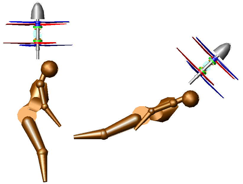
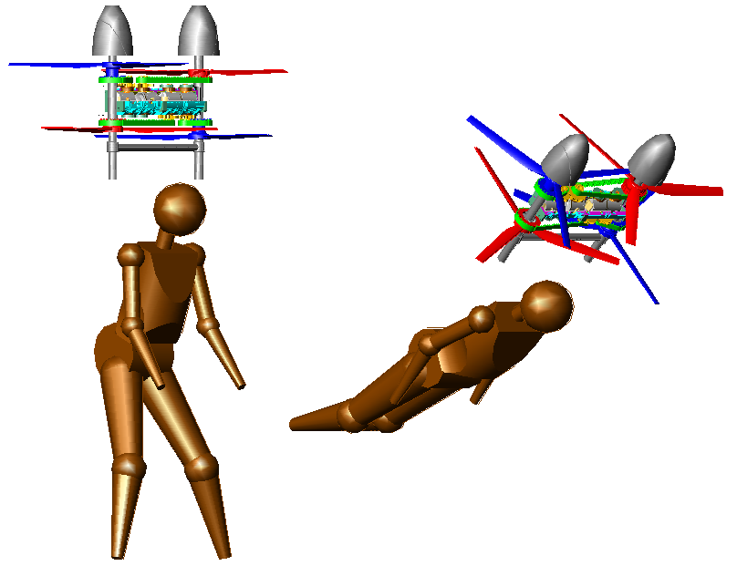
Your flyer only has one thrustvector which can tilt, but this will not fully solve the issue. You can prevent fliping over by tilting your flyer, but that causes a sideways movement. So a more or less stable hover similar to a helicopter is not possible with your setup.”


With three thrust sources, you don’t need thrust vectoring, only individually adjustable thrust.

With one only thrust source, you need adjustable thrust vectoring and adjustable thrust.


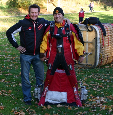
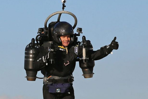
Take Zapata’s JetPack.

He has one only thrust: the jets are parallel to each other and are controlled by the same ”throttle”. They are more than one only for safety reasons (when one fails, the rest provide thrust for a safe landing).
Only for his yaw control Zapata needs a pair of thrust vectoring nozzles.


Take Mayman’s JB-10 JetPack, that with the two only jets.

Image

He has only two thrust sources, not three. And these two thrust sources are parallel to each other (behaving as a single central thrust source).
If Mayman had only one jet, it could not be centrally located.


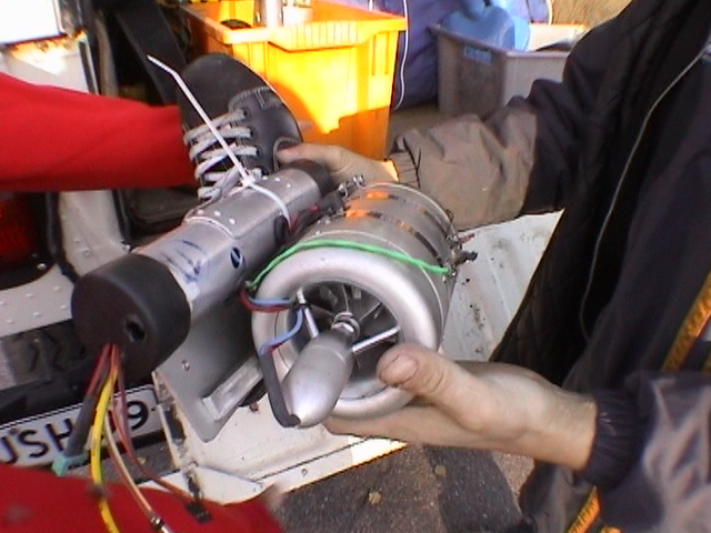
Take a peroxide JetPack:

Image

and count the number of independently vectored thrust sources.


So, a stable hover similar to a helicopter is possible with the Portable Flyer. Unless the videos of Zapata, Mayman and Rossy, wherein they achieve more stable hovering than helicopters, are fake.


You also write:
“Something different though. So you say, your Flyer can carry a Person of 90kg. Your specified dry weight is 20kg and the lift capabilty with one engine out is 115kp or about 113kg...You do know what dry weight means, right? I mean 90+20=110...So you recon 3kg of fuel is enough for 2 hours of flight time or how do i have to understand this?

These is a separate reserve tank containing 2 - 3 litters of fuel.

At an engine stall, the heavy pilot gets rid of the rest fuel and lands with the fuel in the reserve tank.

Thanks
Manolis Pattakos

denktank
denktank
1
Joined: 25 Apr 2015, 19:18

Re: 2 stroke thread (with occasional F1 relevance!)

Post

Richard brown jetpack RR pegasus design

Dr. Acula
Dr. Acula
46
Joined: 28 Jul 2018, 13:23

Re: 2 stroke thread (with occasional F1 relevance!)

Post

manolis wrote:
20 Apr 2020, 08:00
Take Mayman’s JB-10 JetPack, that with the two only jets.
Yes, but look exactly where his thrusters are located, aren't hey strangely far forward? A human body has it's CoG at about navel hight, about halfway in from the naval to the spine. He carries a pretty heavy backpack, so where do you think the common CoG will be?
He designed that thing in a way, that the thrusters are nearly perfectly in line with the common CoG to minimize exactly the problem i discribed. the further away the common thrustvector from the CoG is the worse the problem gets, because you would need to tilt the thrust vector more to compensate which induces a stronger movement.
In the end the question is how easy it will be to be slow enough for a safe landing. The nearer the thrust vector is to the CoG the easier it gets.

manolis
manolis
107
Joined: 18 Mar 2014, 10:00

Re: 2 stroke thread (with occasional F1 relevance!)

Post

Hello DrAcula.

You write:
”Yes, but look exactly where his thrusters are located, aren't hey strangely far forward? A human body has it's CoG at about navel hight, about halfway in from the naval to the spine. He carries a pretty heavy backpack, so where do you think the common CoG will be?
He designed that thing in a way, that the thrusters are nearly perfectly in line with the common CoG to minimize exactly the problem i discribed. the further away the common thrustvector from the CoG is the worse the problem gets, because you would need to tilt the thrust vector more to compensate which induces a stronger movement.
In the end the question is how easy it will be to be slow enough for a safe landing. The nearer the thrust vector is to the CoG the easier it gets.”


Since you agree that:
  • “with a unique, but vectoring, thrust source a Flying Device can take-off (and land) controllably, can hover controllably, and can fly controllably”,
please explain it to Rodak.

The only requirement is the overall CoG (center of gravity) to be close to the “thruster” (i.e. to the axis of the force from the thrust source) and to be displaceable relative to the thruster direction.


Now the question turns to:
“and what prevents the overall CoG of the Portable Flyer from being “nearly perfectly aligned with the thruster”?


In the following images

Image

Image

the same scene is shown from two different view points. At left the pilot is ready to take-off vertically (with the thrust axis vertical and passing from the overall CoG, while at right is at horizontal cruising, again with the thrust axis passing from the CoG.

The CoG can be “nearly perfectly aligned with the thruster”.

And the thruster is easily (and widely) displaceable (weight displacement control) around the CoG.

Do you see any reason for being the Mayman JetPack more stable or more controllable than the Portable Flyer?

The contrary is the case: Mayman is slow in “corrections” because his center of gravity cannot be widely (and quickly) displaced relative to the combined thrust axis. His body is about as heavy as his JetPack - fuel tank weight.

Compare the response of Mayman’s JetPack with Zapata’s JetPack.

Zapata is literally dancing on the air.


Why?
Because bending a little his legs, Zapata causes a big displacement of the thrust axis relative to his center of gravity.

See in the above video, from 1':52'' to 2':02'', Fraky Zapata accelerating and then decelerating with his FlyBoard Air.

Did you ever see Mayman doing, with his JetPack, something similar?

And do you see any reason for being the Zapata JetPack more stable or more controllable or more responsible than the Portable Flyer?

On the contrary, while Zapata is based exclusively on the “weight displacement control” (the pair of “control fins” at the exits of two of its jet-turbines is only for the yaw control), the pilot of the Portable Flyer besides the “weight displacement control” has also aerodynamic control over his flight, because he is inside the high speed downwash of the propellers.

Thanks
Manolis Pattakos

gruntguru
gruntguru
563
Joined: 21 Feb 2009, 07:43

Re: 2 stroke thread (with occasional F1 relevance!)

Post

Rather than "weight displacement control" I would describe this as vectoring of the thrust - raisng one foot relative to the other to "roll" the system and raising or lowering the toes to "pitch" the system.

I don't know whether he has tried it yet but Zapata is certainly at the point where he could transition to horizontal flight wearing a wing suit.
je suis charlie

manolis
manolis
107
Joined: 18 Mar 2014, 10:00

Re: 2 stroke thread (with occasional F1 relevance!)

Post

Hello Gruntguru.

You write:
“Rather than "weight displacement control" I would describe this as vectoring of the thrust - raisng one foot relative to the other to "roll" the system and raising or lowering the toes to "pitch" the system.”

What is displaced (linearly and angularly) is not the weight, but the thrust axis.
So yes, it is "vectoring of the thrust" and not "weight displacement", but most people cannot get the difference.


You also write:
“I don't know whether he has tried it yet but Zapata is certainly at the point where he could transition to horizontal flight wearing a wing suit.”

Visa Parvianen did it, with jets, long ago (25 October 2009):

Quote from https://www.dropzone.com/articles/news/ ... ight-r601/ :

The exit was stable and on-heading, after attaining normal bird-man flight, Visa requested full power from the engines, which responded smoothly in horizontal acceleration. After checking the altimeter several times, it was apparent that there was no appreciable loss in altitude for this period of time. Visa next changed his angle of attack by redirected the thrust and changing his body position to attain vertical climb. This caused a loss in horizontal speed, and stalled (the body?). Recovering from the stall was made easy because of the agility of the human body to change flight profile easily.

Image

Image

End of quote.

Thanks
Manolis Pattakos

manolis
manolis
107
Joined: 18 Mar 2014, 10:00

Re: 2 stroke thread (with occasional F1 relevance!)

Post

Hello all.

The following video


shows Zapata's FlyBoard-Water making loops.

Select "slow motion" (say, at 0.25 reproduction speed) and see from 20" to 25".

Look at the direction of the exiting water beams (it is the direction of the thrust force).

Spot on how much offset (relative to the overall center of gravity) the thrust force is during most of the loop, and how vertical it turns (with small offset) when the guy's head is upwards (because besides the torque for the loops, he also needs an upwards push - from time to time - to prevent him from descending).


Zapata's agility with his FlyBoard-Air is similar, if not better.
But he is not yet performing loops with his FlyBoard-Air.
Maybe he keeps this aerobatic for later.

Thanks
Manolis Pattakos

manolis
manolis
107
Joined: 18 Mar 2014, 10:00

Re: 2 stroke thread (with occasional F1 relevance!)

Post

Hello all.

Here is the PatVRA, a "Vibrations Reduction Apparatus" in a straight-four plane-crankshaft engine, i.e. in a typical 4-cylinder engine (the flywheel is shown transparent):

Image

As the "cross-plane" crankshaft sraight-four engines (Yamaha-R1, motoGP), the above Vibrations Reduction mechanism prevents inertia torque pulses from passing to the transmission and load, without sacrificing the advantages of the typical plane-crankshaft straight-four engine.

The crankshaft of the engine is coupled to the transmission via a phaser introducing a waving, along a crankshaft rotation, angle difference:

Image

between the crankshaft and the output shaft..

Image

Image

Image

Image


For more: https://www.pattakon.com/pattakonVRA.htm

Thanks
Manolis Pattakos

User avatar
nzjrs
60
Joined: 07 Jan 2015, 11:21
Location: Redacted

Re: 2 stroke thread (with occasional F1 relevance!)

Post

manolis wrote:
24 Apr 2020, 04:38
The following video
shows Zapata's FlyBoard-Water making loops.
No real comment on the rest of this discussion other than I've ridden one of these water flyboards.

My experience was; if you can snowboard or skateboard you can pick it up in 15 mins. If you've done neither, I watched people take almost a full day to stand up.

Other than that, my feeling on the board was the hose connecting the board to the Jetski adds a lot of damping in 2 axes. Intuitive really, you can see that in the acrobatics he chooses to do.

gruntguru
gruntguru
563
Joined: 21 Feb 2009, 07:43

Re: 2 stroke thread (with occasional F1 relevance!)

Post

manolis wrote:
29 Apr 2020, 13:36
Here is the PatVRA, a "Vibrations Reduction Apparatus"
Brilliant. (works like the Hyundai CVVD valve phaser)
je suis charlie

manolis
manolis
107
Joined: 18 Mar 2014, 10:00

Re: 2 stroke thread (with occasional F1 relevance!)

Post

Thank you Gruntguru.

It is the same mechanism with the PatVVD (more at https://www.pattakon.com/pattakonVVD.htm ):

Image

Image

Image

Image

Image

In the one case the mechanism "setup" (defined by the lengths of the various links) is to create a basically 2nd order phase difference:

Image

in the other case is to create a basically 1st order phase difference:

Image

Thanks
Manolis Pattakos

User avatar
PlatinumZealot
551
Joined: 12 Jun 2008, 03:45

Re: 2 stroke thread (with occasional F1 relevance!)

Post

I understand your system... But man your assembly drawings are hard to read!

Is the fact tha Hyndai uses slots and you use two linkages enough to differentiate your design?
🖐️✌️☝️👀👌✍️🐎🏆🙏

gruntguru
gruntguru
563
Joined: 21 Feb 2009, 07:43

Re: 2 stroke thread (with occasional F1 relevance!)

Post

A lot of sliding friction in those slots although the Rover system has been around for 24 years and seems reliable.
je suis charlie

manolis
manolis
107
Joined: 18 Mar 2014, 10:00

Re: 2 stroke thread (with occasional F1 relevance!)

Post

Hello PlatinumZealot.

You write:
"I understand your system...


Explaining the patVVD:

The cyan part is the cam shaft whereon a cam lobe is pivotally mounted; the cyam cam shaft rotates at constant angular velocity.

The patVVD mechanism (not shown here***) causes a fluctuation of the angular velocity of the cam lobe along a camshaft rotation.

Image

(slow motion at https://www.pattakon.com/VVD/PatVVD_explained_slow.gif )

The animation has a slide per 6 degrees of camshaft rotation (or per 12 degrees of crankshaft rotation).

At a first position of the control pin (not shown) the camlobe (shown red in this case) rotates slowly when its nose passes over the "for more: www.pattakon.com" label (at bottom), and quickly when its nose passes over the "patVVD : pattakon CVVD" label (at top).

At a second position of the control pin, the camlobe (shown blue in this case) rotates quickly when its nose passes over the "for more: www.pattakon.com" label (at bottom), and slowly when its nose passes over the "patVVD : pattakon CVVD" label (at top).

If the valve actuator were where the bottom label is, the valve duration with the control pin at its first position (cam lobe red) would be more than 70 camshaft degrees longer than with the control pin at its second position (cam lobe blue).”

***the mechanism is explained by a windows “exe” animation at thebottompf the https://www.pattakon.com/pattakonVVD.htm web page.


You also write:
"But man your assembly drawings are hard to read!"

They are not "assembly drawings".
They are "patent drawings".
Isn't the "single cylinder" simple and simple to get?


By the way:

the PatRoVa rotary valve :

Image

is by far simpler,can be variable, and has a few times higher rev limit than the patVVD,

while the DVVA (desmodromic VVA):

Image

is way more variable and has substantially higher rev limit than the patVVD.

But as compared to

"Hyundai’s Breakthrough Engine that Answers a 133-year Challenge"!! (more at theirofficial web page at : https://tech.hyundaimotorgroup.com/arti ... challenge/),

the patVVD has significantl differences and advantages.

Thanks
Manolis Pattakos

manolis
manolis
107
Joined: 18 Mar 2014, 10:00

Re: 2 stroke thread (with occasional F1 relevance!)

Post

Hello all.

Perfectly controlled hovering:


Thanks
Manolis Pattakos