2 stroke thread (with occasional F1 relevance!)

All that has to do with the power train, gearbox, clutch, fuels and lubricants, etc. Generally the mechanical side of Formula One.
LucF
LucF
0
Joined: 29 May 2015, 11:35

Re: 2 stroke thread (with occasional F1 relevance!)

Post

manolis wrote:Hello LucF.

Given that Ryger knows that a technical solution officially filed in a patent office is protected, what is all this “secrecy” for?

The 80% less emissions is not an answer; it is an advertising trick.
Unless Ryger engine has 80% less emissions than the “current 2-stroke” Rotax 800 E-TEC.
He could simply give the gr/kWh of HC, CO, NOx and CO2 at some conditions.

The same for the “can go far more than 30k” while its breathing capacity (power) drops after 18,000rpm. Suppose it “can go far more than 50k or 100,000rpm”; then what?


You write:
“For new engine designs keep always in mind the following.
All nice designs you show us, but all to complicated and therefore to expensive to introduce in this automotive world.”

Thanks for the advise and for the opportunity to explain how things are.

Thanks
Manolis Pattakos
Thanks again Manolis, for the most interesting engine designs, but sorry, I think you don't know what is realy simple.
I don't gonna explain it, because everybody can see, that these doesn't fits what I wrote before.

The biggest advantages of the Ryger engine are:
1. 80% less emmissons,
2. Very simple to change almost all existing engines into a Ryger engine,
3. Much more power over a very wide rpm range, so much lighter engine with the same power.

You also try to give a change to what I wrote:
Never wrote its completaly clean,
never wrote its 80% cleaner than Rotax 800 E-TEC
Simple to find is this : http://www.rygerengine.com/index.emissions.htm

And it is not you or anyone else to decide what or when mr Ryger should do.
If you were in his place you also would not accept that, do you ....?

Sorry for all readers that I can't tell more at this moment, I hope this will change soon.
If so I will post it immediately.

Kind regards, Luc

LucF
LucF
0
Joined: 29 May 2015, 11:35

Re: 2 stroke thread (with occasional F1 relevance!)

Post

gruntguru wrote:
LucF wrote:
manolis wrote: Hello LucF
Tell Harry Ryger that after applying for a patent, the inventor can reveal to the public his “patent pending” (which means “protected if a patent will eventually be granted”) invention without risk.

Why do you think you are the only one to know this?
Perhaps Manolis (like most of us here) is struggling to understand why it is not possible to post details of the engine here when it is supposedly protected by the patent system.

The claims sound wonderful but this is a technical forum and we are more interested in technical detail. We can find all the claims we want elsewhere.
Have you ever seen the claims all together in one design?

manolis
manolis
107
Joined: 18 Mar 2014, 10:00

Re: 2 stroke thread (with occasional F1 relevance!)

Post

Hello LucF.

You write:
“And it is not you or anyone else to decide what or when mr Ryger should do.
If you were in his place you also would not accept that, do you ....?”

If I were in his place, I would decide either to reveal my idea to the public or to keep it secret. The one of the two.


You also write:
“You also try to give a change to what I wrote:
Never wrote its completaly clean,
never wrote its 80% cleaner than Rotax 800 E-TEC
Simple to find is this : http://www.rygerengine.com/index.emissions.htm

On one hand you keep referring to Harry Ryger as “mr. Ryger”, on the other hand you are ready to accuse those not accepting the unjustified / tricky claims of Ryger.

In your post of August 24, 2015, you write:
“When the word "clean" is used it was meant in comparison with the current 2 stroke design.”

Can you, please, define the “current 2 stroke design”?
And what excludes the Rotax 800 E-TEC 2-stroke from the “current 2 stroke design”?


Regarding the emissions:

Note for the following photo:
At left is the test for the "kz2 engine original", at right is the test for the "Ryger engine"
The first day the HC of the kz2 were "out of scale".
The second day it was measured, again, the "kz2 engine original", this time at 13,680ppm HC.

Image

It is strange that the 13,680ppm HC of the “kz2 engine original” and the 3,319 ppm HC of the Ryger engine agree so well with the “80% less emissions” you keep claiming as "the biggest advantage of the Ryger engine" according your:

"The biggest advantages of the Ryger engine are:
1. 80% less emmissons,
2. Very simple to change almost all existing engines into a Ryger engine,
3. Much more power over a very wide rpm range, so much lighter engine with the same power."


I hope I am wrong, but if your reference engine is the above “kz2 engine original” (which, according your link, emits so much HC that the first day the Sun MGA tester was “blocked”) something goes wrong with the entire Ryger engine project.

Just to mention that 700ppm HC is the limit for the non-catalytic cars made before 1986 (and 100 ppm HC is the limit for the catalytic cars).

According the previous, an old (made before 1986) non-catalytic car engine reduces the emissions of the “Ryger clean twostroke engine” by 80%, while a catalytic car engine reduces the emissions of the "Ryger clean twostroke engine" by 97%.


Do I miss something?


At the end, is the "Ryger engine concept" about making a true-green modern engine or about reducing the emissions of a cart twostroke?


Thanks
Manolis Pattakos

LucF
LucF
0
Joined: 29 May 2015, 11:35

Re: 2 stroke thread (with occasional F1 relevance!)

Post

Thanks Manolis,
For all your answers and new questions.
For now I have to be silent till the moment of publication.
So please have a little patient.

Kind regards, Luc Foekema

J.A.W.
J.A.W.
109
Joined: 01 Sep 2014, 05:10
Location: Altair IV.

Re: 2 stroke thread (with occasional F1 relevance!)

Post

For now I have to be silent till the moment of publication.
So please have a little patient.

Kind regards, Luc Foekema[/quote]


Must you really be such a tease, L-F?

Why bother, with such a hype/secret squirrel approach?
"Well, we knocked the bastard off!"

Ed Hilary on being 1st to top Mt Everest,
(& 1st to do a surface traverse across Antarctica,
in good Kiwi style - riding a Massey Ferguson farm
tractor - with a few extemporised mod's to hack the task).

manolis
manolis
107
Joined: 18 Mar 2014, 10:00

Re: 2 stroke thread (with occasional F1 relevance!)

Post

Sleeve-valves vs Opposed Pistons

Hello.

I was looking at this:

Image

arrangement of Rolls-Royce Crecy 2-stroke as a solution for modern 2-strokes.

The sleeve valves of R-R Crecy move at double frequency than the sleeve valves of the Bristol Radials 4-strokes:

Image

While the angular oscillation of the Bristol sleeve valves about their cylinder axes offers a significant functional advantage (maximization of the valve-time-area), this is not the case for the Crecy 2-strokes sleeve valves wherein the angular oscillation just increases the inertia loads and the friction.

In both cases it is required a strange connection between the sleeve valve and its actuator.

In both cases (R-R Crecy and Bristol sleeve) the sleeve valve is supported asymmetrically causing flexing and increasing the friction.

While the sealing of the combustion chamber of the Bristol sleeve valve engine is based on normal rings on the moving piston and on the stationary “piston”, in the Crecy R-R design the sealing of the top side of the combustion chamber is based on the tight fit of the sleeve valve top-end with the cylinder.


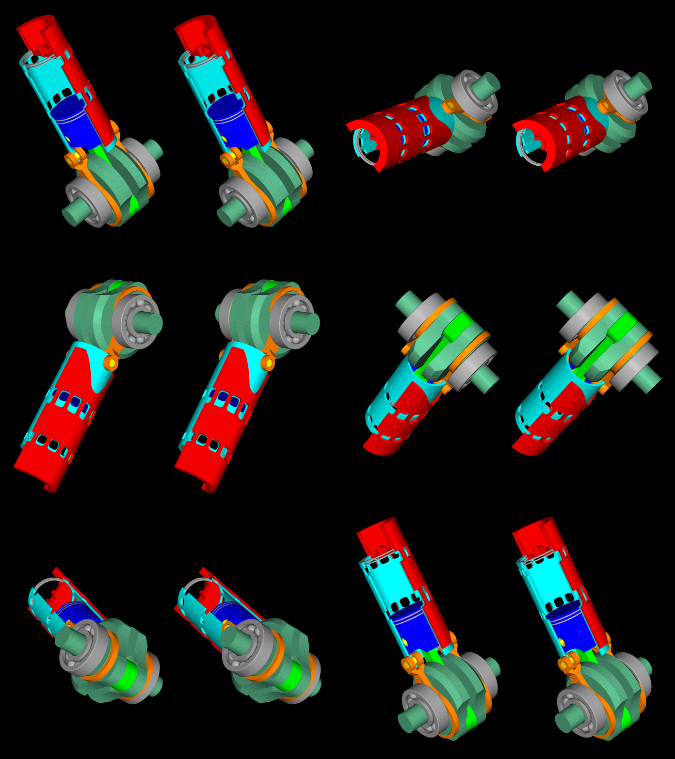
A better solution seems this:
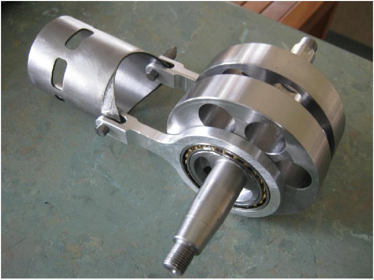
Image

It is from a prototype sleeve valve two-stroke engine made by Uniflow (F1 Technical Forum).

As compared to Crecy sleeve valve, it is symmetrically supported by a pair of auxiliary side-connecting rods on two slim crankpins of small eccentricity, avoiding the angular oscillation about the cylinder axis.

A common problem with the R-R Crecy is the scavenging efficiency of the top part of the combustion chamber.
Even in the giant Marine two strokes (wherein the stroke is several times bigger than the bore) a core of residual hot gas remains along / around the axis of the cylinder (in this case the exhaust is at the opposite end of the cylinder and not in the middle of the cylinder).

A common problem is also the need for long stroke to bore ratios to put the transfer and exhaust ports away from each other (to avoid short circuit). The small distance of the transfer port from the top of the above sleeve valve shows the problem.


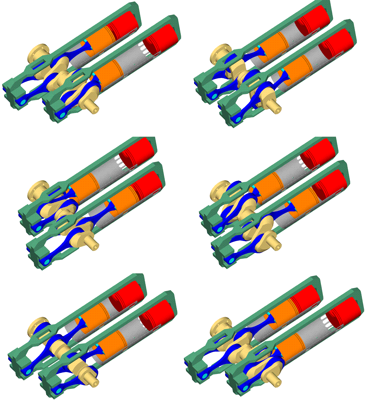
A better solution seems this design:
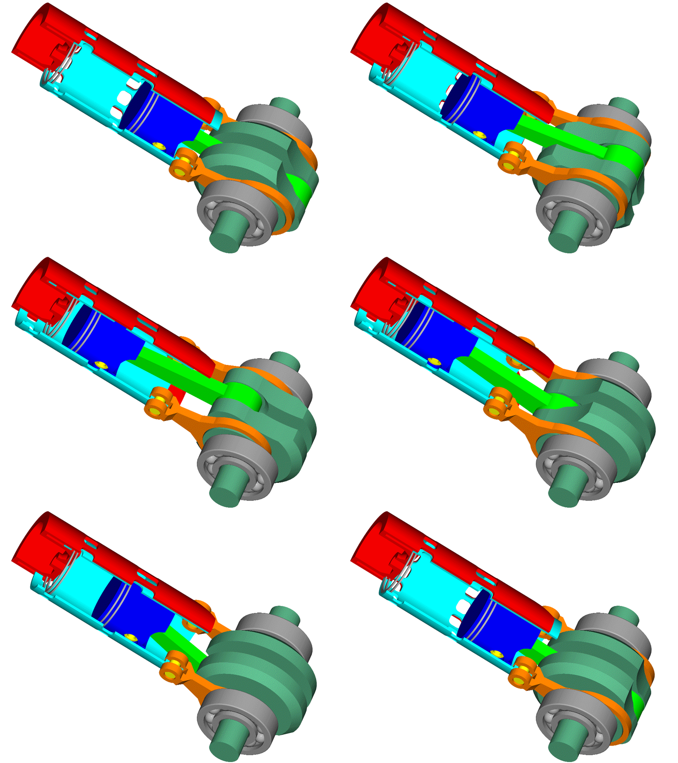
Image

Image

At http://www.pattakon.com/Sleeve/Sleeve3.gif amd http://www.pattakon.com/Sleeve/Sleeve3_STE.gif are the above animations at full size.

For windows users the "exe" program at http://www.pattakon.com/Sleeve/Sleeve2.exe may be interesting.

(the second animation can be seen stereoscopically according the instructions at http://www.pattakon.com/pattakonStereoscopy.htm )

Besides the simple actuation of the sleeve valve (Uniflow), it also offers the sealing quality of the Bristol sleeve valve design wherein a stationary piston at the top of the cylinder has piston rings sliding on the sleeve valve. No tight fit between the sleeve valve and the cylinder is required.

With the exhaust ports at the top of the cylinder, the scavenging is more efficient (fewer residual gas, lower cycle temperatures).

It seems a good solution.
But, as in the previous cases, it needs a long piston stroke.
A long piston stroke means heavier inertia loads, more friction, lower rev limit and less power.

A common disadvantage in all previous cases is the increase of the inertia loads and of the vibrations (the heavy sleeve valve reciprocates in synchronization with the piston; the first order inertia force of the reciprocating piston adds with the first order inertia force from the reciprocating sleeve valve). A single cylinder would vibrate a lot more than a conventional single cylinder 2-stroke (same piston, same connecting rod, same stroke, same rpm).


A better solution is to put in motion the immovable piston of the last arrangement.
This is what the Junkers-Doxford does:
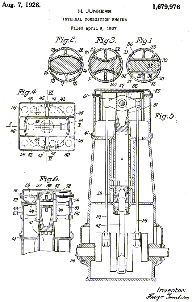
Image

Instead of using the side connecting rods for the sleeve valve, now the side connecting rods are used for the top piston.

The sleeve valve is eliminated together with the associated friction; the lubricant consumption reduces; the friction reduces (two pistons moving at half stroke).

The first order inertia forces are fully balanced.


A better solution is the OPOC (Opposed Piston, Opposed Cylinder engine) of Ecomotors (Bill Gates is one of their famous investors): two Junkers-Dosford share the same crankshaft for the sake of full balance:
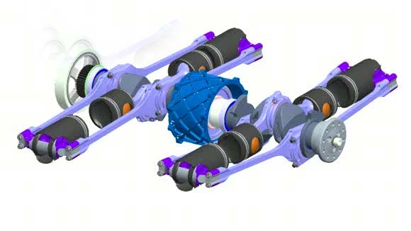
Image


A better solution is the PatPOC engine:
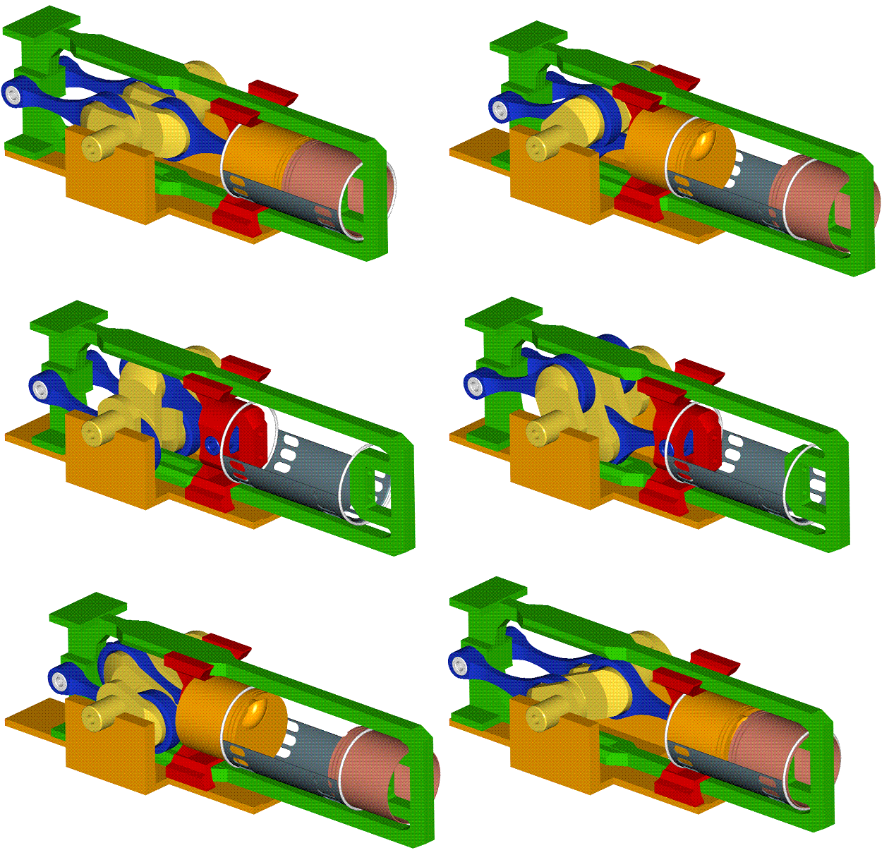
Image

Image

(more at http://www.pattakon.com/pattakonPatPOC.htm ; spot on the short crankshaft: the crankpins can be inside the cylinder footprint).


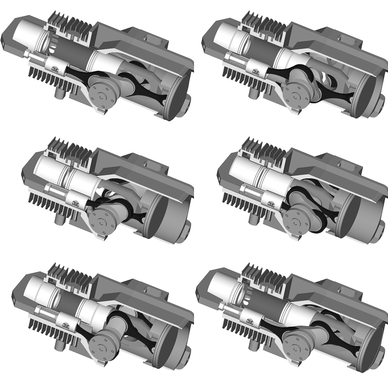
A better solution is also the PatOP engine:
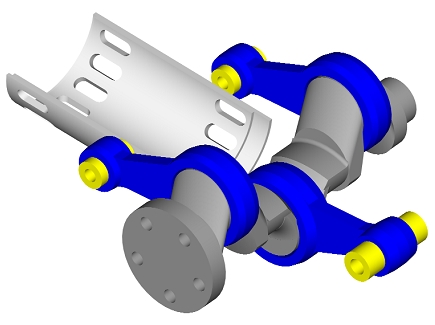
Image

Image

Image

(more at http://www.pattakon.com/pattakonPatOP.htm )

Among others it reduces the overall height of the engine, it takes the thrust loads on surfaces rid of ports, it has “four-stroke-like” lubrication, it has built-in piston-type scavenging pump etc.
The “pulling rod” architecture of the PatOP increases substantially the piston dwell around the combustion dead center (think what this means for a high revving Diesel)

Worth to mention that the main bearings of the crankshaft of all abovementioned Opposed Piston engines can run unloaded (think why); theoretically you can hold by your hands the crankshaft at operation.


Thoughts?
Objections?

Thanks
Manolis Pattakos

autogyro
autogyro
53
Joined: 04 Oct 2009, 15:03

Re: 2 stroke thread (with occasional F1 relevance!)

Post

Brilliant descriptions Manolis.
How about replacing the two side locator pistons with linear generator/starters?
Would make the basis for a very compact hybrid system.

manolis
manolis
107
Joined: 18 Mar 2014, 10:00

Re: 2 stroke thread (with occasional F1 relevance!)

Post

Hello Aurogyro and thanks.

In order to absorb the power of the PatOP engine you need big and heavy linear generators / starters to convert directly to electricity a good part of the energy provided to the pistons during the expansion cycle, without first passing this energy to the crankshaft.
You will also need an oppositely moving linear generator (say secured on the big piston of the scavenging pump) to balance the others two.
The heavy linear generators limit the rev limit and the power; they are also expensive as compared to conventional (rotating) electric generators.

I think that a conventional generator / flywheel driven directly by the crankshaft is cheaper, simpler and more efficient.


On the other hand there is a way better solution for gen-sets: the OPRE Opposed Piston with the two counter-rotating crankshafts:

Image

(video at http://www.pattakon.com/pre/OPRE5.MOV , more at http://www.pattakon.com/pattakonOPRE.htm )

Replacing the two big flywheels by two conventional counter-rotating electric generators / starters you have, among others, the most vibration-free gen-set.
The basis of this gen-set is perfectly rid of inertia vibrations and of combustion vibrations and of reaction torque.
And all these, with one only cylinder.

Thanks
Manolis Pattakos
J.A.W.
J.A.W.
109
Joined: 01 Sep 2014, 05:10
Location: Altair IV.

Re: 2 stroke thread (with occasional F1 relevance!)

Post

Here's another opposed piston 2T CI GA aero-mill, claims a "BSFC of .38"..

http://www.geminidiesel.aero/why-diesel ... l-solution
"Well, we knocked the bastard off!"

Ed Hilary on being 1st to top Mt Everest,
(& 1st to do a surface traverse across Antarctica,
in good Kiwi style - riding a Massey Ferguson farm
tractor - with a few extemporised mod's to hack the task).

riff_raff
riff_raff
132
Joined: 24 Dec 2004, 10:18

Re: 2 stroke thread (with occasional F1 relevance!)

Post

A very creative concept, but unfortunately I can't see how it provides a real improvement over existing commercial recip engines when all factors are considered, especially cost. I see a four throw crankshaft, five pistons, four conrods, two cylinder blocks, a crosshead, a cylinder head, four rod bearings, four wrist pins, three main bearings, and a crankcase. All of this for a single working cylinder having two opposed pistons.
"Q: How do you make a small fortune in racing?
A: Start with a large one!"

gruntguru
gruntguru
563
Joined: 21 Feb 2009, 07:43

Re: 2 stroke thread (with occasional F1 relevance!)

Post

riff_raff wrote:A very creative concept, but unfortunately I can't see how it provides a real improvement over existing commercial recip engines when all factors are considered, especially cost. I see a four throw crankshaft, five pistons, four conrods, two cylinder blocks, a crosshead, a cylinder head, four rod bearings, four wrist pins, three main bearings, and a crankcase. All of this for a single working cylinder having two opposed pistons.
Opposed piston is well established as perhaps the ultimate 2 stroke layout. If you look at the history - Junkers Jumo, Commer Knocker and Ecomotors OPOC there are many advantages and simplifications in Manolis' elegant PatOP. Try and think of a simpler, more compact layout for a single cylinder opposed engine. Does it include a scavenge pump?

BTW there are 3 pistons. The two little ones are crosshead bearings. Crosshead piston constraint is icing on the cake.
je suis charlie

manolis
manolis
107
Joined: 18 Mar 2014, 10:00

Re: 2 stroke thread (with occasional F1 relevance!)

Post

Hello Gruntguru and thank you.


The “pulling rod” arrangement (the connecting rods are loaded in tension during the combustion) offers a 30% longer piston dwell at the combustion dead center of the PatOP (and of the OPRE, which is the dual-crankshaft “father” of the PatOP) Opposed Piston.
This provides extra time for more efficient combustion of the fuel (the combustion completes at higher expansion ratios) and allows higher revving direct injection Diesels (more power, wider rev range).

Quote from http://www.pattakon.com/pattakonOPRE2.htm :

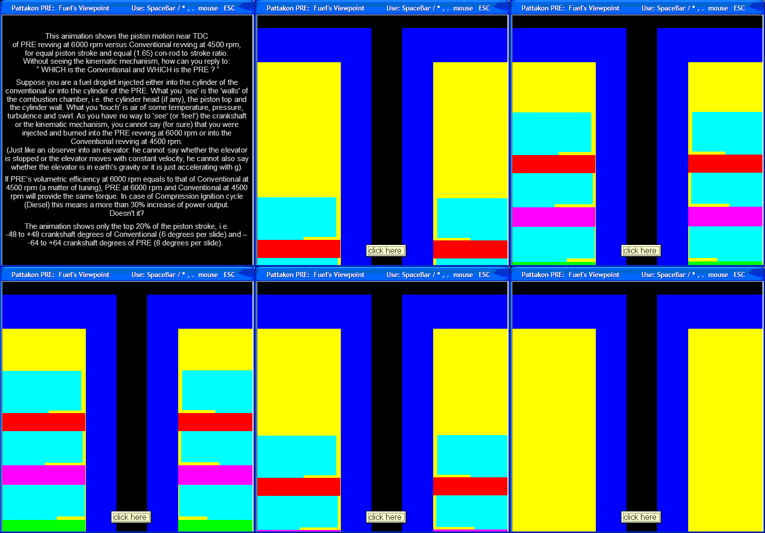
“Fuel's Viewpoint
This animation shows the piston motion near TDC of PRE revving at 6000 rpm versus Conventional revving at 4500 rpm, for equal piston stroke and equal (1.65) con-rod to stroke ratio.

Image

Without seeing the kinematic mechanism, how can you reply to: " WHICH is the Conventional and WHICH is the PRE ? "
Suppose you are a fuel droplet injected either into the cylinder of the conventional or into the cylinder of the PRE. What you 'see' is the 'walls' of the combustion chamber, i.e. the cylinder head (if any), the piston top and the cylinder wall. What you 'touch' is air of some temperature, pressure, turbulence and swirl. As you have no way to 'see' (or 'feel') the crankshaft or the kinematic mechanism, you cannot say (for sure) that you were injected and burned into the PRE revving at 6000 rpm or into the Conventional revving at 4500 rpm.”

End of quote.


Another big issue is the lubrication.

Quote from http://www.pattakon.com/pattakonOPRE.htm :

“The transfer of the wrist pin - i.e. of the thrust loads - away from the hot combustion chamber and away from the ports, solves another problem of the opposed piston engines: it allows "four stroke" like lubrication and oil consumption.
. . .
In comparison, the piston skirt of the conventional opposed piston engine thrusts heavily onto the hot, especially at exhaust side, cylinder wall, around the port area where the openings restrict the contact surface, requiring plenty of lubricant and inevitably resulting in lubricant consumption.”

Thanks
Manolis Pattakos

J.A.W.
J.A.W.
109
Joined: 01 Sep 2014, 05:10
Location: Altair IV.

Re: 2 stroke thread (with occasional F1 relevance!)

Post

Some interesting pioneering 2T doings from Riedel here.. http://www.odd-bike.com/2014/05/imme-r1 ... esign.html
"Well, we knocked the bastard off!"

Ed Hilary on being 1st to top Mt Everest,
(& 1st to do a surface traverse across Antarctica,
in good Kiwi style - riding a Massey Ferguson farm
tractor - with a few extemporised mod's to hack the task).

manolis
manolis
107
Joined: 18 Mar 2014, 10:00

Re: 2 stroke thread (with occasional F1 relevance!)

Post

Hello J.A.W. and thanks for the link

Quote from your link about Riedel:

“At some point in the late 1930s or early 1940s Riedel, now working for Victoria-Werke in Nuremburg, designed a two-stroke, horizontally-opposed air-cooled twin which would serve as the starter for these production turbojets. This compact 270cc engine, named the Riedel Anlassermotor (starter motor), featured a remarkably oversquare design with a 70mm bore and 35mm stroke and produced 10hp at 6000rpm, with power transferred from the crankshaft through a series of planetary gears to a stepped gear which meshed with the central shaft of the turbine.

Image

End if quote


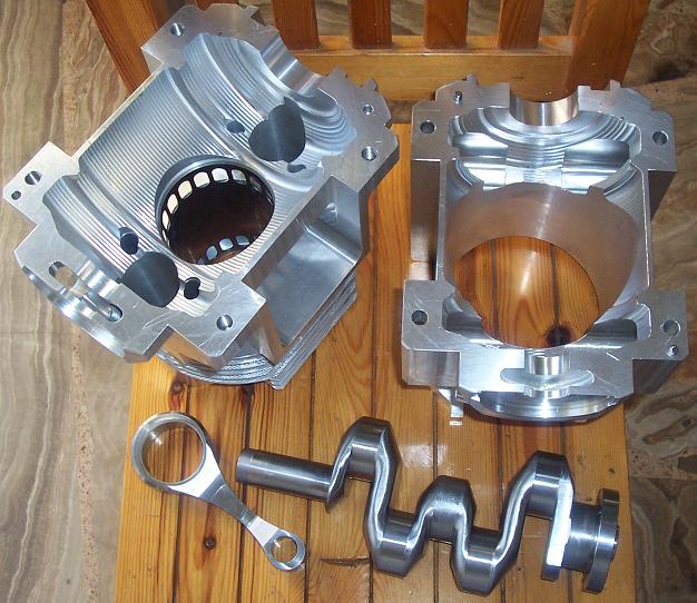
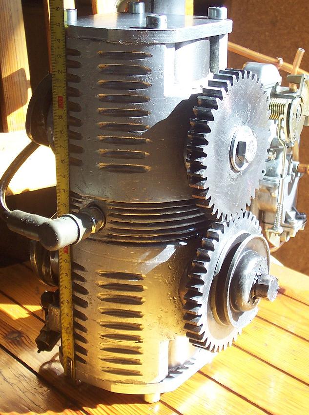
Here is the first prototype of the Opposed Piston OPRE Tilting:

Image

It has an even-more-oversquare design and exploits it for cross-through scavenging:

333 cc,
bore 84mm, stroke 30+30=60mm,
weight: 8.5Kp (19lb) without the exhaust pipe and the carburetor
height: 250mm.

Here is a later design:

Image

and here:

Image

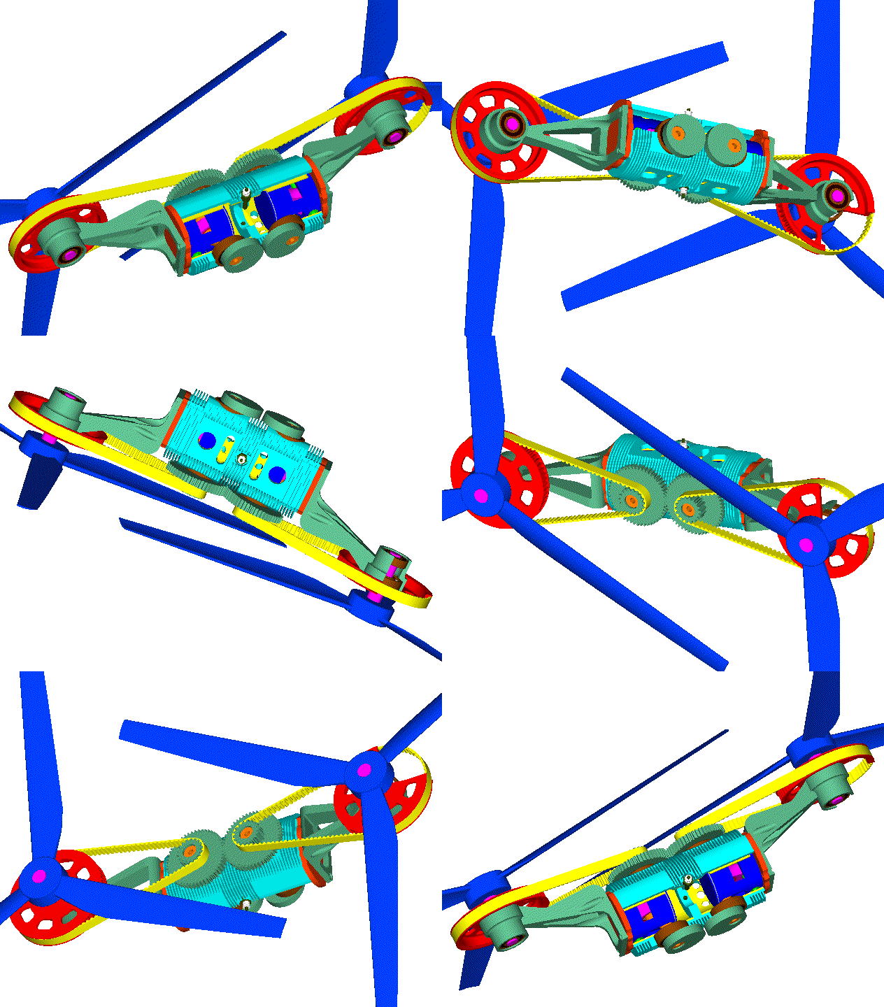
is an application of it for Portable Flyers, Paragliding, small airplanes etc (more at http://www.pattakon.com/pattakonFly.htm and http://www.pattakon.com/pattakonTilting.htm )

With sprockets and toothed belts (a common practice for small high-revving aero engines like Simonini / http://www.pattakon.com/tempman/Simonin ... g230cc.jpg ), two counter-rotating large diameter intermeshing propellers mounted at the same side of the OPRE Tilting engine are revving at substantially lower, than the engine, revs.

The small stroke enables high and reliable revving (with 30mm piston stroke - i.e. with total stroke 30+30=60mm - the mean piston speed at 12.000rpm is only 12m/sec).

At operation, the two synchronizing gearwheels of the OPRE Tilting engine run unloaded (each crankshaft drives its own propeller).

The basis of the above propulsion unit needs not to provide any reaction torque; besides being perfectly vibration-free (including all types of inertia and combustion vibrations), it also has zero gyroscopic rigidity.

Thanks
Manolis Pattakos
nokivasara
nokivasara
2
Joined: 27 Nov 2014, 20:53

Re: 2 stroke thread (with occasional F1 relevance!)

Post

Chainsaws and garden equipment of today uses something that's called stratified scavenging, with two sets of intake ports as I understand it, to create a layer of clean air in the transfer port which is used to push out the exhaust gasses. I'm not sure I have understood it correctly, but it sounds like a good way for decreasing emissions and improving fuel efficiency.

Here's some more info:
http://www.freepatentsonline.com/8833316.html
https://www.youtube.com/watch?v=IY7zQKw4qsQ

What's your take on it?