Page 1 of 2
How to simulate this car chassis ? please help
Posted: 23 Jul 2016, 19:04
by firasf1dream
hello everyone,
i am trying to simulate this f1 chassis which i modeled in solidworks, so i need please your help in where to place the forces exactly for a 2G braking ?
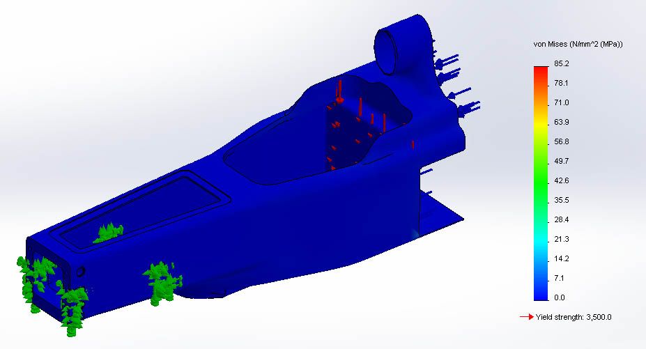
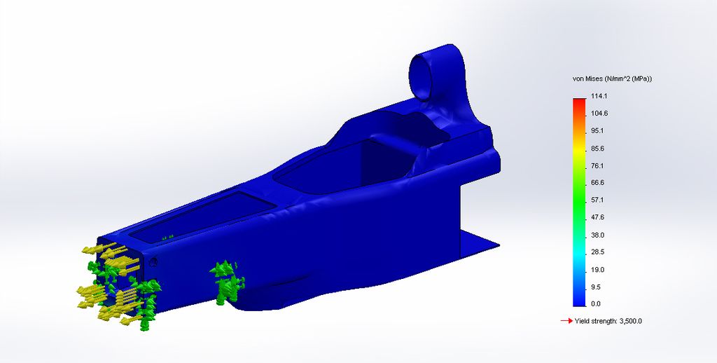
below is a picture which i tried before using a composite material shell with 3 layers of 1 mm each and a configuration of 0 degree for the moment for the 3 layers. The forces you see in the picture are reactions which i calculated before in x direction to the front and in z downward but i do not know if these should be the ones for a 2g braking ? i applied them at the back but i feel that it is wrong help me please
thanks in advance
Re: How to simulate this car chassis ? please help
Posted: 23 Jul 2016, 22:56
by Greg Locock
In non exhaustive detail you need to consider where the masses are in the sprung body, the front to rear brake force distribution, and, really the compliance in the surrounding structures.
At the very least you should draw free body diagrams so you understand how the forces balance out across the tub.
Re: How to simulate this car chassis ? please help
Posted: 24 Jul 2016, 00:10
by firasf1dream
Greg Locock wrote:In non exhaustive detail you need to consider where the masses are in the sprung body, the front to rear brake force distribution, and, really the compliance in the surrounding structures.
At the very least you should draw free body diagrams so you understand how the forces balance out across the tub.
Hello GregLocock,
thank you for your reply, this is a report i am writing for my final project, i am a mechanical engineering student but we don't take any automotive course whatsoever, so all are personal research in this field of F1, so my problem is understanding where and how to enter the forces applied to the chassis in the software which is SolidWorks
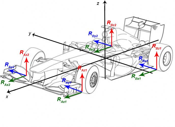
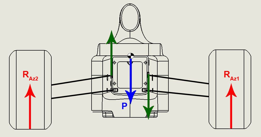
here is a picture that shows how i placed the forces on the wheels ( let me know please if anything wrong) and the picture after shows a torque applied when steering anti-clockwise or clockwise depends of the steering direction
about the second picture the way i understand it is this : when you steer to the left let's say, the weight will go to the right so the bigger reaction force will be on the right and the chassis looking at it from the front will have a clockwise torque so for simulation i decided to fix the back surface of the cockpit and apply forces on the points of suspension connection to make the torque and see how this fiberglass monocoque will react
Re: How to simulate this car chassis ? please help
Posted: 24 Jul 2016, 08:32
by Greg Locock
I suggest you reread my previous post. Stealing other people's illustrations is no substitute for an FBD.
Re: How to simulate this car chassis ? please help
Posted: 24 Jul 2016, 10:29
by firasf1dream
Greg Locock wrote:I suggest you reread my previous post. Stealing other people's illustrations is no substitute for an FBD.
Stealing ? what do you mean stealing ? the first one, i got the car from google and places the forces and axes using photoshop and the second one i made it from scratch ! using my models in solidworks and made the drawing out of it
Re: How to simulate this car chassis ? please help
Posted: 24 Jul 2016, 11:37
by mep
As quick draft, that’s how I would start it:
1. Different driving situations (braking, acceleration, cornering, combined) will give you a bunch of different cases which you need to prove the stiffness for. Calculate the individual wheel forces for these driving situations. Also include some multipliers for dynamic events (curbs etc.). Generally this is the physical part of the project.
2. From the wheel forces calculate the reaction forces in each suspension pick up point (wishbone, rocker, damper, track rod). This step is very mathematical but makes the difference.
3. The reaction forces can be applied to your chassis model.
4. The mounting positions at your back face can be restrained
So far you have transferred the occurring wheel forces through your monocoque to the rearward part of the chassis. What is ignored so far is the mass of the chassis and individual parts mounted to it. It is up to you how much you want to go into detail with this but for sure there is a relative heavy driver sitting in the chassis generating relevant force.
5. Calculate the forces the driver mass is generating when exposed to external g-loads. Also take into account that the driver can generate significant brake force and an equivalent reaction force to the seat.
6. Also apply these forces to your chassis.
7. Repeat step 5 and 6 for all relevant masses.
The major difference to your approach is that you can only know and calculate the external wheel forces. The wheels are where the car is resting on. From this you work your way to the chassis over the suspension geometry which is splitting up the wheel forces into individual forces which are much higher. Then you apply additional forces to represent localized masses. Still it’s a simplified model and can always be questioned and I am looking forward to it.

Re: How to simulate this car chassis ? please help
Posted: 24 Jul 2016, 13:13
by firasf1dream
mep wrote:As quick draft, that’s how I would start it:
1. Different driving situations (braking, acceleration, cornering, combined) will give you a bunch of different cases which you need to prove the stiffness for. Calculate the individual wheel forces for these driving situations. Also include some multipliers for dynamic events (curbs etc.). Generally this is the physical part of the project.
2. From the wheel forces calculate the reaction forces in each suspension pick up point (wishbone, rocker, damper, track rod). This step is very mathematical but makes the difference.
3. The reaction forces can be applied to your chassis model.
4. The mounting positions at your back face can be restrained
So far you have transferred the occurring wheel forces through your monocoque to the rearward part of the chassis. What is ignored so far is the mass of the chassis and individual parts mounted to it. It is up to you how much you want to go into detail with this but for sure there is a relative heavy driver sitting in the chassis generating relevant force.
5. Calculate the forces the driver mass is generating when exposed to external g-loads. Also take into account that the driver can generate significant brake force and an equivalent reaction force to the seat.
6. Also apply these forces to your chassis.
7. Repeat step 5 and 6 for all relevant masses.
The major difference to your approach is that you can only know and calculate the external wheel forces. The wheels are where the car is resting on. From this you work your way to the chassis over the suspension geometry which is splitting up the wheel forces into individual forces which are much higher. Then you apply additional forces to represent localized masses. Still it’s a simplified model and can always be questioned and I am looking forward to it.
Hello mep,
thank you so much for your help and the resume you gave me

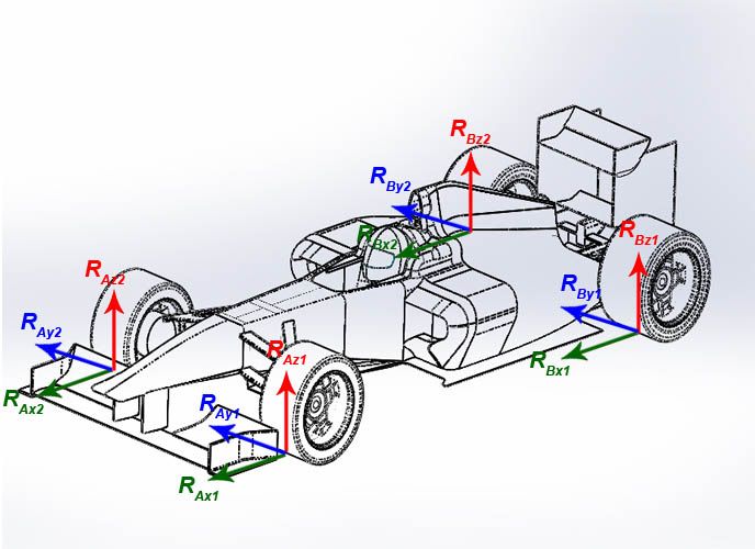
i think after what you said i am on the right track, first i would like to tell you that this model is scaled 1/4 custom with a considered mass of 20kg to be on the safe side so no driver is included therefore no seat and braking reaction for the driver needed so the picture below (to be clear for Greg

if he means the model well i am using a model i made before original model which will include in the report so he no stealing here whatsoever) first picture is mine 101%.
second mep the calculation i made so far are exactly what you said about the distribution of forces thank you for confirming i did calcuylate these before on braking on acceleration on cornering and while the car is static
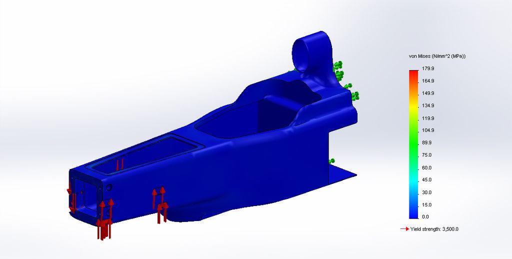
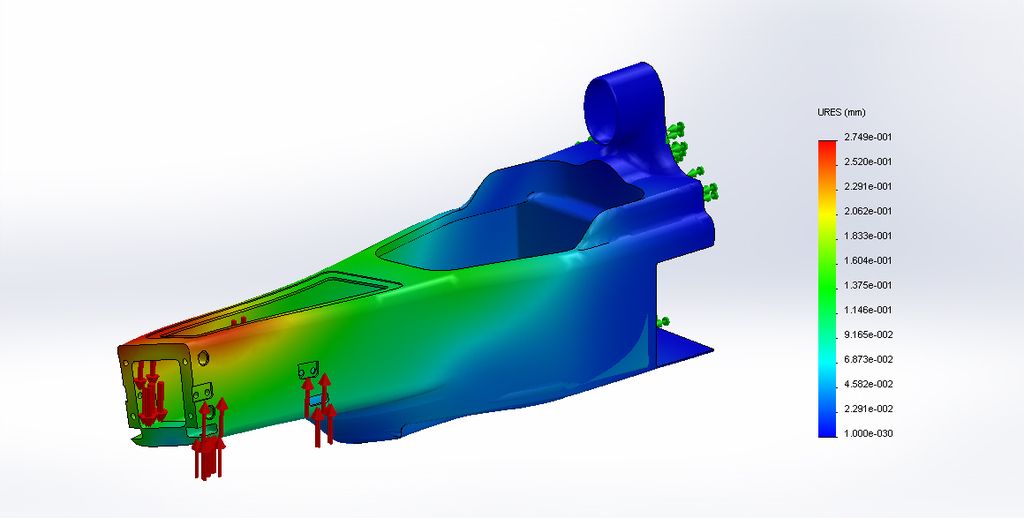
so here are my simulation and the way i saw it, about cornering i fixed the back face of the chassis as you confirmed now and i applied the highest cornering force i got from calculation on the connection points of the suspensions as for braking i applied a 2g*20 kg force on the front face which is pushing in the forward direction and fixed the suspension connecting points, i applied this setup for 2 configurations of fiber : [0/0/0] and [45/0/-45] and the results i got were in the not static model of course the second configuration
Re: How to simulate this car chassis ? please help
Posted: 05 Aug 2016, 20:22
by PlatinumZealot
That does not look correct though.
There is a jacking force from both front wheels.
For the aero loading on the entire car you have to add both front and back and get the resultant force and a moment force and apply this as well to the chassis. This magnitude depends on the the location.
There is also a force from the body of the driver in the car. His weight pushing on the front bulk head.
I haven't tried composite simulations in solidworks.. I am not even so sure how solidworks handles it. I know ANSYS can handle it quite good where you can put in the directional properties of the layup and such, but that is over my head for now.
Re: How to simulate this car chassis ? please help
Posted: 06 Aug 2016, 09:40
by ChrisDanger
Is your yield strength 3.5 GPa?!
Can Solidworks similate anisotropic materials? If not, will these results be representative?
Re: How to simulate this car chassis ? please help
Posted: 06 Aug 2016, 10:48
by krisfx
I tried (stupidly) simulating a composite component using the carbon fibre material in Solidworks while at university, it didn't seem at all accurate
Re: How to simulate this car chassis ? please help
Posted: 19 Aug 2016, 17:48
by firasf1dream
PlatinumZealot wrote:That does not look correct though.
There is a jacking force from both front wheels.
For the aero loading on the entire car you have to add both front and back and get the resultant force and a moment force and apply this as well to the chassis. This magnitude depends on the the location.
There is also a force from the body of the driver in the car. His weight pushing on the front bulk head.
I haven't tried composite simulations in solidworks.. I am not even so sure how solidworks handles it. I know ANSYS can handle it quite good where you can put in the directional properties of the layup and such, but that is over my head for now.
hello PlatinumZealot,
thanks for your reply, about the weight i can assure you it is added to the car because i used a higher weight than for the actual car, and this will not have any driver in it because it's a scaled car 1/4, when i did the simulation for the aerodynamics i got a value of -20.703 N which means additional weight is added to the car and it will stay pushed to the ground while in straight
Re: How to simulate this car chassis ? please help
Posted: 19 Aug 2016, 17:49
by firasf1dream
ChrisDanger wrote:Is your yield strength 3.5 GPa?!
Can Solidworks similate anisotropic materials? If not, will these results be representative?
yes it is, 3500 MPa, it a value i got from many sources for the E-glass fiber
Re: How to simulate this car chassis ? please help
Posted: 19 Aug 2016, 17:51
by firasf1dream
krisfx wrote:I tried (stupidly) simulating a composite component using the carbon fibre material in Solidworks while at university, it didn't seem at all accurate
why ? i got realistic values which has a very similar behavior in reality
Re: How to simulate this car chassis ? please help
Posted: 19 Aug 2016, 18:08
by mrluke
Silly question.
Under a steering condition, is it correct to put the reaction forces at the points where the wishbones enter the chassis? I would have thought the forces would travel through the spring / damper mounts with the wishbones acting as pivot points. This would clearly be different for braking.
Re: How to simulate this car chassis ? please help
Posted: 19 Aug 2016, 18:12
by firasf1dream
mrluke wrote:Silly question.
Under a steering condition, is it correct to put the reaction forces at the points where the wishbones enter the chassis? I would have thought the forces would travel through the spring / damper mounts with the wishbones acting as pivot points. This would clearly be different for braking.
why is it a silly question if i never ever made a study for a single seater car or any car and i am trying to learn !!?!