Page 1 of 1
Where to start when designing an F1 chassis?
Posted: 20 Aug 2010, 02:44
by nlacosta93
Where should one begin to design an Formula One car chassis after the safety cell? I have a basic safety cell 3d drawing complete following the FIA Technical Regulations for 2010. Suggestions?
Re: Where to start when designing an F1 chassis?
Posted: 20 Aug 2010, 20:16
by Tonn
Welcome to f1technical, nice to see new members!
Could you upload some pictures
If you want I have some 3D boxes (front and rear wing and diffuser) that shows allowed bodywork in these areas
I am using these boxes to control my car legality
Keep it up!!!
Re: Where to start when designing an F1 chassis?
Posted: 20 Aug 2010, 21:56
by nlacosta93
This is just the safety cell according to the FIA Rules for 2010 with no aerodynamic features w/ the headrest (i don't know the proper name for that).

Re: Where to start when designing an F1 chassis?
Posted: 21 Aug 2010, 01:03
by Just_a_fan
I think the safety cell also includes the fuel tank. Or at least, the fuel tank should be within the safety cell if that makes more sense. Therefore your tub needs to extend further rearwards. The rear face of the new bit is the surface to which the drive train is then mounted.
Re: Where to start when designing an F1 chassis?
Posted: 21 Aug 2010, 02:56
by nlacosta93
Yes I know I just haven't designed the roll bar yet, that's why there isn't a fuel tank area behind the driver area.
Re: Where to start when designing an F1 chassis?
Posted: 21 Aug 2010, 03:22
by marcush.
without thinking outof the box ,Neweys v-shape of the tubis not possible...it is of course another question if the idea itself is that important.
Re: Where to start when designing an F1 chassis?
Posted: 21 Aug 2010, 05:48
by nlacosta93
Added some curvature to the chassis and headrest

This should give me a start on the roll structure
Re: Where to start when designing an F1 chassis?
Posted: 23 Aug 2010, 22:54
by Edis
The fuel tank and rollbar/engine air intake is part of the tub, so can also the cooling air inlets. The engine is bolted directly on the back of the tub. The gearbox carries the rear suspention and the front suspension is attached to the tub. Cooling ducts and radiators are attached to the sides of the tub.
In front of the tub is the nosecone/front crashbox where the front wing is attached. On the gearbox the rear crashbox is attached. Under the tub is then ballast attached, then there is the floor section and the plank.
The rear bodywork is composed of the engine cover, and then there is the rear wing attached to the rear crashbox.
Inside a tub
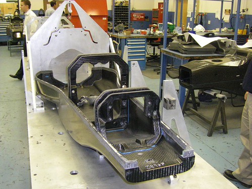
Tub manufacturing

Re: Where to start when designing an F1 chassis?
Posted: 25 Aug 2010, 19:24
by Richied76
Hi, i'm sure i've seen more of these pics somewhere else on the forum but cant find them. can anyone point me in the right direction
Re: Where to start when designing an F1 chassis?
Posted: 25 Aug 2010, 21:13
by marcush.
as you can see the structure to hold the confor foam is not part of the tub ,its only bonded panels .
Is your tub buck already at the permitted maximum width towards the engine interface/bulkhead?this will determine how long your tub will have to be to accomodate the required tank size..you may check with Nick Wirth....
tub design has to consider manufacturing feasibility as well ..is your plan to have top and bottom halves bonded together?
what about the required bulkheads some of them can be integrated .
avery interesting part will be how to mate the engine to the tub..How much does
an aluminium engine expand from room temp to working temp?the Carbon tub is unlikely to grow..
Re: Where to start when designing an F1 chassis?
Posted: 25 Aug 2010, 22:07
by 747heavy
Re: Where to start when designing an F1 chassis?
Posted: 26 Aug 2010, 00:16
by marcush.
and this of course...with the hint at RedBulls R&D into flexi parts....
http://www.racecar-engineering.com/news ... y-q-a.html
