To learn and share about dampers / shock absorbers

Here are our CFD links and discussions about aerodynamics, suspension, driver safety and tyres. Please stick to F1 on this forum.
Greg Locock
233
Joined: 30 Jun 2012, 00:48

Re: To learn and share about dampers / shock absorbers

Post

Image

http://www.mediafire.com/view/xlimpi480 ... resis2.JPG

Image

Image

Well sorry i can't get the image to display. The direct link should work

Greg Locock
233
Joined: 30 Jun 2012, 00:48

Re: To learn and share about dampers / shock absorbers

Post

OK, here's one with a tiny amount of backlash in it.

https://www.mediafire.com/?538xp919qmz3yyg

Hope that works

Yawpower
1
Joined: 28 Feb 2014, 06:49

Re: To learn and share about dampers / shock absorbers

Post

Greg Locock wrote:I can get the same effect with a simple model if I put a negative stiffness in series with the damper, but that is a bit silly.
Yup. Academic, and maybe even silly, especially if you are not building dampers, but your "negative stiffness" gives strong clues as to the reasons that it may be observed in a damper.

Maybe DaveW will tell us how this "negative hysteresis" might effect a vehicle on his rig.

Greg Locock
233
Joined: 30 Jun 2012, 00:48

Re: To learn and share about dampers / shock absorbers

Post

You may have missed my subsequent reply, backlash also gives a twisted loop effect.

ChrisDanger
26
Joined: 30 Mar 2011, 09:59

Re: To learn and share about dampers / shock absorbers

Post

Just for interest, a bit more on the nonlinearity of a typical force vs velocity curve at higher speeds...

I remember seeing a demonstration during an Aussie V8 Supercar race where a rig had been set up of a see-through damper. They ran it at speeds typical of those seen while racing, and at the highest speeds (while riding the curbs) cavitation was present, much like that shown below.

(Jump to 0:47 or open in YouTube)

Yawpower
1
Joined: 28 Feb 2014, 06:49

Re: To learn and share about dampers / shock absorbers

Post

Greg Locock wrote:You may have missed my subsequent reply, backlash also gives a twisted loop effect.
I did miss it. And now I'm trying to wrap my head around it.

Thank you.

Greg Locock
233
Joined: 30 Jun 2012, 00:48

Re: To learn and share about dampers / shock absorbers

Post

Backlash is a CAE modeller's nightmare. We often put springs and dampers across the clearance to try and keep the model sane. If I could go through my models and get rid of all the friction (another bloody mathematical nightmare), backlash and other step type non linearities my models would run ten times faster. We even have a more graceful step function that tries to soften the impact of the non linearity, basically it rounds the corners off.

DaveW
239
Joined: 14 Apr 2009, 12:27

Re: To learn and share about dampers / shock absorbers

Post

Yawpower wrote:
Greg Locock wrote:I think that's friction/compliance.
I agree that below 1.25 ips the spread can be attributed to static friction, but what about above 1.25 ips? The damping force at a given velocity is greater while accelerating than while decelerating. The opposite of what you would expect from compliance.
I think Greg could well be correct.

It would take a while to demonstrate why I believe that. The short form might be shown by the following plots. Both were extracted from a simulated rig test carried on a "mechanical" car.

Figure 1 shows the reconstructed front damper plot extracted from model results (model is good because I know the structure and parameters of the model). The trajectory shown in red is the pure damper; that shown in green is the effect of a 2.8 KN/mm series compliance (a typical racing shock would be expected to be around 3.5 KN/mm).

Figure 2 is exactly the same data. The red plot is a repeat of the green trajectory shown in Figure 1; now the green plot contains the results obtained by identifying the spring stiffness. The only difference between the two trajectories is the estimated stiffness ("Slope" is 106 compared with 117.19). Incidentally, the higher number is incorrect because the identifying model was incorrect....

Arguably, the green plot of Figure 2 looks quite like the trajectory you posted. If you agree, then I would suggest that the answer to your implied question might be found in your Dyno & the way the data was processed.

RideRate
7
Joined: 02 Jun 2009, 19:49

Re: To learn and share about dampers / shock absorbers

Post

Yawpower wrote:I believe that "negative hysteresis" was mentioned earlier in this thread. Possibly this image will spark further conversation.
You have "normal" hysteresis around zero which is where the bulk of the stiffness we talk about has an effect during a sine wave test. This is because, as a mechanically compliant item, the rate of change of force with respect to time is greatest and this is what creates the hysteretic behavior here. Above the more transient parts of the test you are nearer to steady state or rather the input is relatively slowly changing. Hysteretic behavior here is more attributable to valving, shims, flow porting, etc. "Negative" hysteresis here is not hard to create. On that note, neither is "positive" hysteresis.

Basically I'm stating the two loops of hysteresis you see are not created by the same phenomenon and both are totally normal and not weird.

RideRate
7
Joined: 02 Jun 2009, 19:49

Re: To learn and share about dampers / shock absorbers

Post

Yawpower wrote:I agree that below 1.25 ips the spread can be attributed to static friction, but what about above 1.25 ips? The damping force at a given velocity is greater while accelerating than while decelerating. The opposite of what you would expect from compliance.
Above 1.25ips on this plot is likely hysteresis in shim deflection. Think of the shims as having frictional behavior in their deflection profile because sometimes they do. As they open they don't deflect as far as they would if there was zero friction. Therefore, coming from the closed position they are biased in the closed direction creating less flow area and more shock force. After you force the shims to max deflection at your peak test speed they now reverse direction and remain biased to the open direction. Thus remaining further open than before as you cross the same speed which increases flow area and reduces force.

The conceptual behavior is like that of a spring/mass system with friction on the mass. You will achieve different displacements for the same force depending on the history of the mass's position.

Ciro
0
Joined: 14 Jun 2020, 22:08

Re: To learn and share about dampers / shock absorbers

Post

How much LMP spec dampers like these ones

Image

can be adopted to hillclimb use on a different chassis of similar weight 750-800kg?
Say a non-aero car of Lotus Elise kind with a suitable pushrod conversion to take care of MR.

marcush
9
Joined: 27 Mar 2021, 19:26

Re: To learn and share about dampers / shock absorbers

Post

These dampers are shimmed for a high downforce car (lmp) and so they are configured for high vertical load , thats possibly double force of what is needed for a non downforce car .....you don't know the motion ratio , of damper/wheel travel is .
a flat bottom lmp car also runs zero droop at the front to keep the front edge of the floor as close ti the ground as possible .
LMP 1/2 uses Carbon brakes so front
bump force damping (low speed damping) needs to be dramatic .
So you will have something like 60 to 100kg springs in a Elise type track car if I remember correctly and these dampers have a lot of adjusters (high speed bump/rebound and low speed bump and rebound . Without a dyno curves its
impossible to know if the shimming and bleed is anywhere near what you need and adjustment range is enough
but first things first here:
fitting these beauties in your car ,you will first need to establish closed and fully extended lengths and compare with what is installed in the car .The fully compressed value cannot(!) be shorter or longer than your original part .droop travel can be less , maybe must be less .
Send a pm if you really want to go ahead with this .

Greg Locock
233
Joined: 30 Jun 2012, 00:48

Re: To learn and share about dampers / shock absorbers

Post

They look like a remote reservoir electrically valved damper. Is that right? They'd be great fun for all sorts of science projects (as we call them). UWA ran with them for FSAE-A a long time ago.

Ciro
0
Joined: 14 Jun 2020, 22:08

Re: To learn and share about dampers / shock absorbers

Post

marcush wrote:
29 Mar 2021, 01:26
These dampers are shimmed for a high downforce car (lmp) and so they are configured for high vertical load , thats possibly double force of what is needed for a non downforce car .....you don't know the motion ratio , of damper/wheel travel is .
a flat bottom lmp car also runs zero droop at the front to keep the front edge of the floor as close ti the ground as possible .
LMP 1/2 uses Carbon brakes so front
bump force damping (low speed damping) needs to be dramatic .
So you will have something like 60 to 100kg springs in a Elise type track car if I remember correctly and these dampers have a lot of adjusters (high speed bump/rebound and low speed bump and rebound . Without a dyno curves its
impossible to know if the shimming and bleed is anywhere near what you need and adjustment range is enough
but first things first here:
fitting these beauties in your car ,you will first need to establish closed and fully extended lengths and compare with what is installed in the car .The fully compressed value cannot(!) be shorter or longer than your original part .droop travel can be less , maybe must be less .
Send a pm if you really want to go ahead with this .
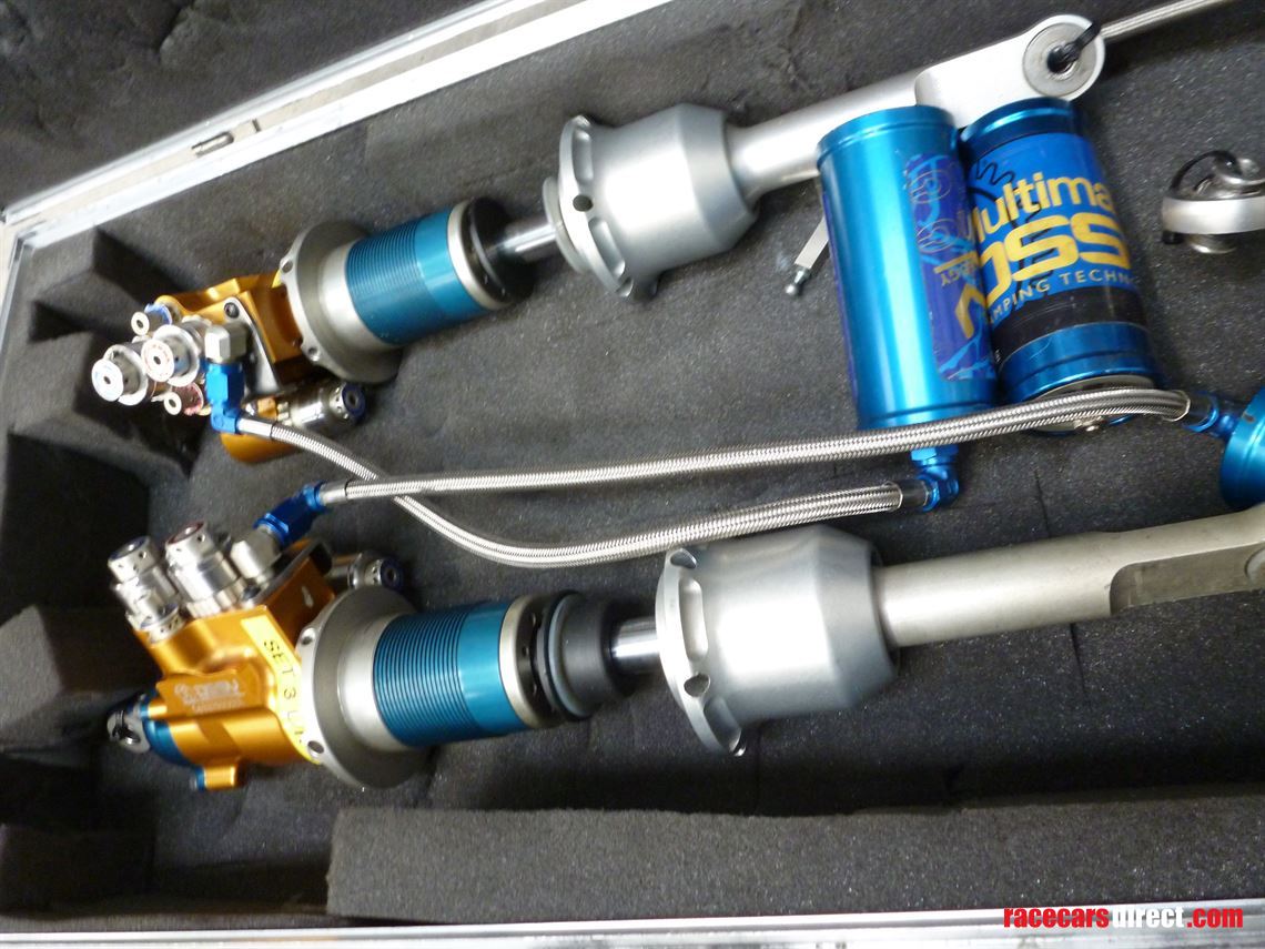
Hello Marcush, glad to hear your reply here. I actually tried a few times sending you PMs but never managed, maybe it is because I am new to this forum, don't really know. A long PM just remained in the outbox.
Send me a mail if that is OK for you tech@naum.design

Does it make sense for the forum community that we explore the possibilities of such setup here? Or in a new thread or ..?

Ciro
0
Joined: 14 Jun 2020, 22:08

Re: To learn and share about dampers / shock absorbers

Post

Greg Locock wrote:
29 Mar 2021, 02:21
They look like a remote reservoir electrically valved damper. Is that right? They'd be great fun for all sorts of science projects (as we call them). UWA ran with them for FSAE-A a long time ago.
Hi Greg
To my knowledge the two dampers in the picture are 5-way adjustable (cartridge blowoff) with "passive" remote reservoir and are from the rear.
Two smaller units with inverters built-in and no springs only bump rubbers are at the front with a reservoir machined with body. The two third elements however have a possibility to use interconnection via an electrically valved unit with separate valving for braking and acceleration.
Imho