I gave you an example with inches and with no springs at all.
I am not an american, I am from the caribbean, we use SI units.
I wouldn't give a spring rate in N/m if i am dealing will cm sized components. My lecturer taught in N/cm2 as well, so i got used to doing that, and i find it more representative than other units. The american system is to bulky and inflexible.
You can't draw back the curtains and give me up, because I am not trying to fool you.
I may very well use 1 million N/cm and the only thing that changes is that i get more restraint.
60,000 N/cm is 34,260 lb/inch
- That 400 mm long, 50 mm Alu bar I used while trying to xplain, would have a "spring rate" of 3 450 000 "N/cm".
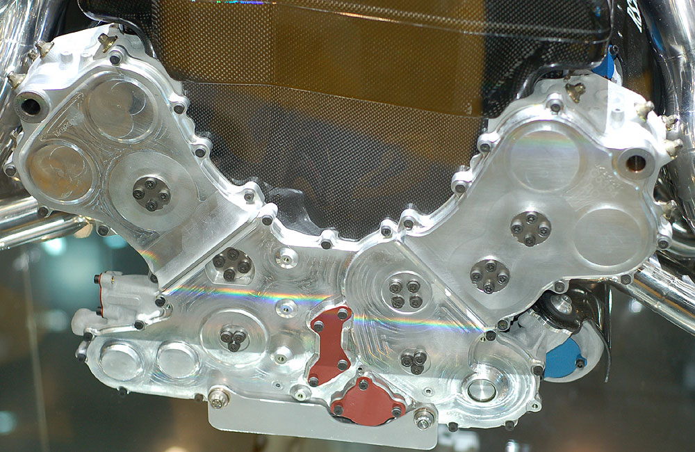
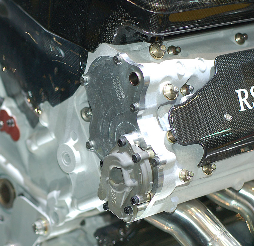
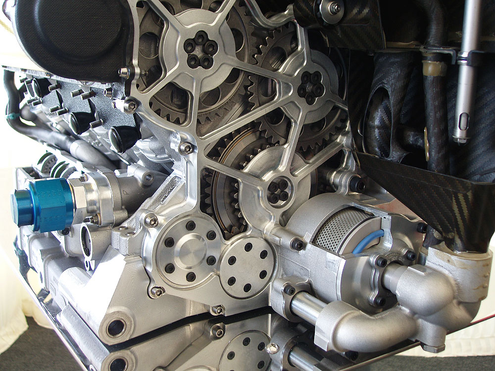
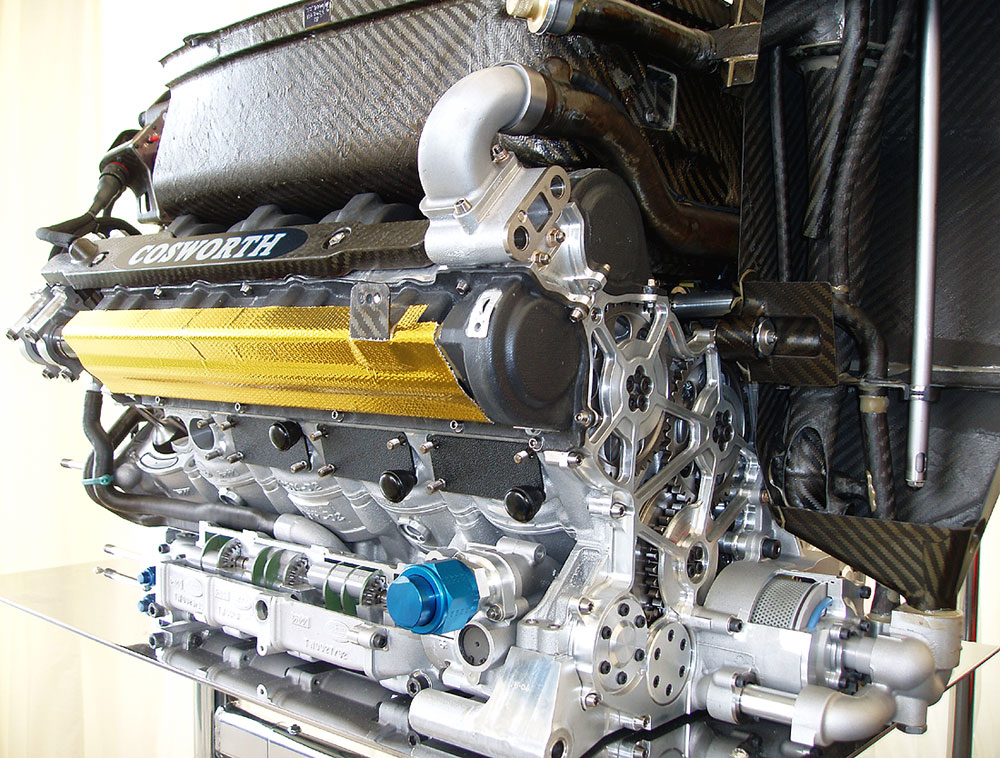
- A skinny 8 mm steel pin-bolt with 50 mm free length, perhaps like in the Cosworth images, should be in the region of
2 000 000 "N/cm", but very flexible laterally, which is the general idea when it comes to cope with thermal xpansion.
All the better for me.
This just makes things easier to prove. The only reason i used a spring instead of another bar, is that i would have to consider the expansion of the other bar as well, then i would have to to a deeper calculation, and no one would bother trying to get the whole meaning of it.
Check out the example without the springs.
One of the first things i learned in strength of materials.
The bar wont be flexible laterally. Why should it?
You're forgetting about the clamping force.

That black washer, is a shoulder washer, that basically holds the bolt straight in the bore and reduces movement.