747heavy wrote:I hope, you don´t consider me arrogant Ringo,
I don´t really have a dog in this fight, just try to learn something.
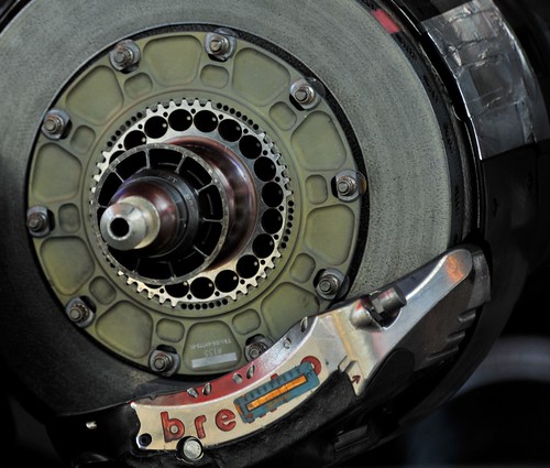
I´m not all that up to date with oad car braking technology, but in allmost every
racing car, I have worked on, the brake disc´s are mounted, so that they can float.
It´s the case with steel disc´s as well, as with carbon disc´s
Well i'm not familiar with race car tech.

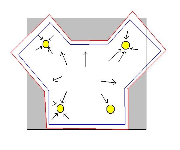
I think these are rigidly fixed at the fasteners, but what i think happens here is that It was designed to have a low contact area to the centre piece, amongst other things it may be the best method to fix 2 disimilar materials such as carbon rotor and magnesium? center.
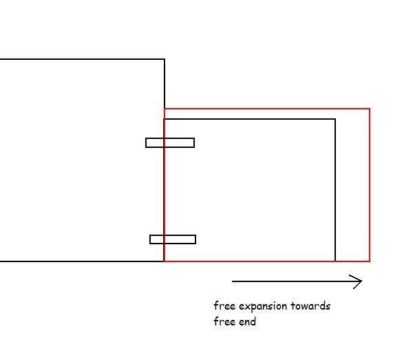
Here is my example where a part can be designed to take thermal expansion. I know this as fact.
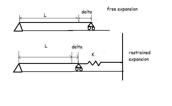
we have a beam of length L and area A fixed at the left end and free to roll at the right end.
Under free thermal expansion with a change in temperature dT, it changes in length by an extension, e
e = alpha*L*dT, alpha being the coefficient of linear thermal expansion.
This beam will not be under any internal stresses since the beam is expanding freely.
In the second case, the right end of the beam is restrained by a spring and wall.
The wall is immovable. Spring constant is k and the spring extends by e.
Force in spring, P = e * K [1]
amount retrained = free expansion - spring extension = alpha*L*dT - e [2]
Agree so far?
for elastic materials:
strain* young's modulus = stress
extension e / length L * E = force P/ area A
P = e*A*E/L [3]
P = (alpha * L * dT - e)* A * E/L substituting [2] in [3]
e * K = (alpha * L * dT - e)* A * E/L substituting [1] in above
solve for e.
e = alpha*dT*A*E/ ( K + AE/L)
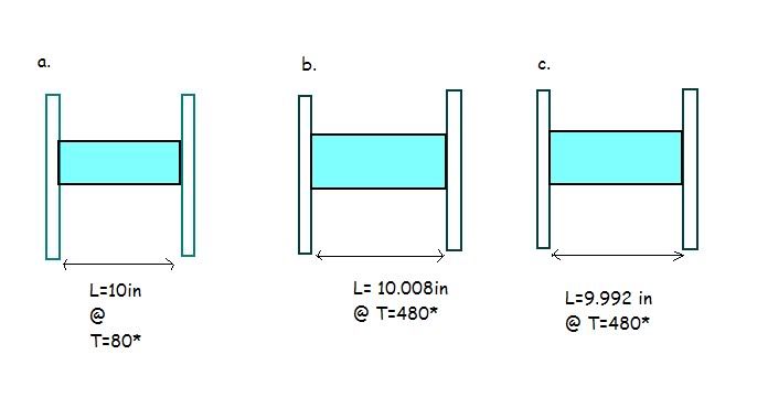
a sample, K= 60000N/cm, dT = 100, A = 1cm^2, E = 2x10⁷ N/cm2, L = 100cm,alpha 10^-6
I went extreme on the K and T.
e = 10^-6 * 100 * 1 * 2* 10^7 / (60000 + 2*10^7/100)
e = 0.0076 cm
force = ke = 461N, stress = 461N/cm2 , way bellow yeild point yet it was restrained
It would have extended to 0.01cm without the spring. That's a factor of 1.3 times.
restraint yes, failure no.
Secondly take note of the order of extension, this is a 1m long rod that only moves out less than a mm.
These guys are over blowing the thermal expansion issue. A motor vehicle engine is child's play in terms of temperature... 100 degrees

The difference with bulk head and engine wot even be that high.