ringo wrote:
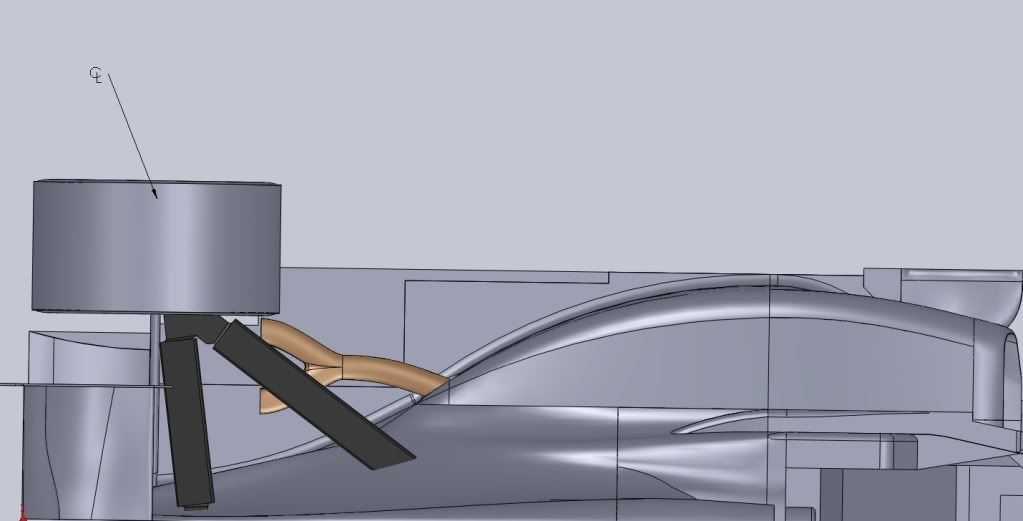
gonna move on now to the gear box end of things and beam wing. Sorry for the snail pace.
No worries. You could always get a job at HRT then
Looking real good.

ringo wrote:
gonna move on now to the gear box end of things and beam wing. Sorry for the snail pace.


I'd be interested in more details, ringo, because (forgive me) I don't think the idea would work, let alone be a "benefit"....ringo wrote:I came up with this concept called cable suspension. Instead of rods, the car is suspended by cable.
There is a cable for compression and one for rebound. This is needed as a cable cannot compress; it can only carry tension. The cables are very thin and are drawn through pulleys inside the gearbox to the torsion springs.
Yes, but.... I once rig tested an Arrows with carbon fibre pull rod front's which turned out to have poor installation stiffness. I was told that the pull rod itself was fine, the difficulty lay in transferring loads to & from it without introducing excessive compliance.MIKEY_! wrote:Go for carbon fiber cables.
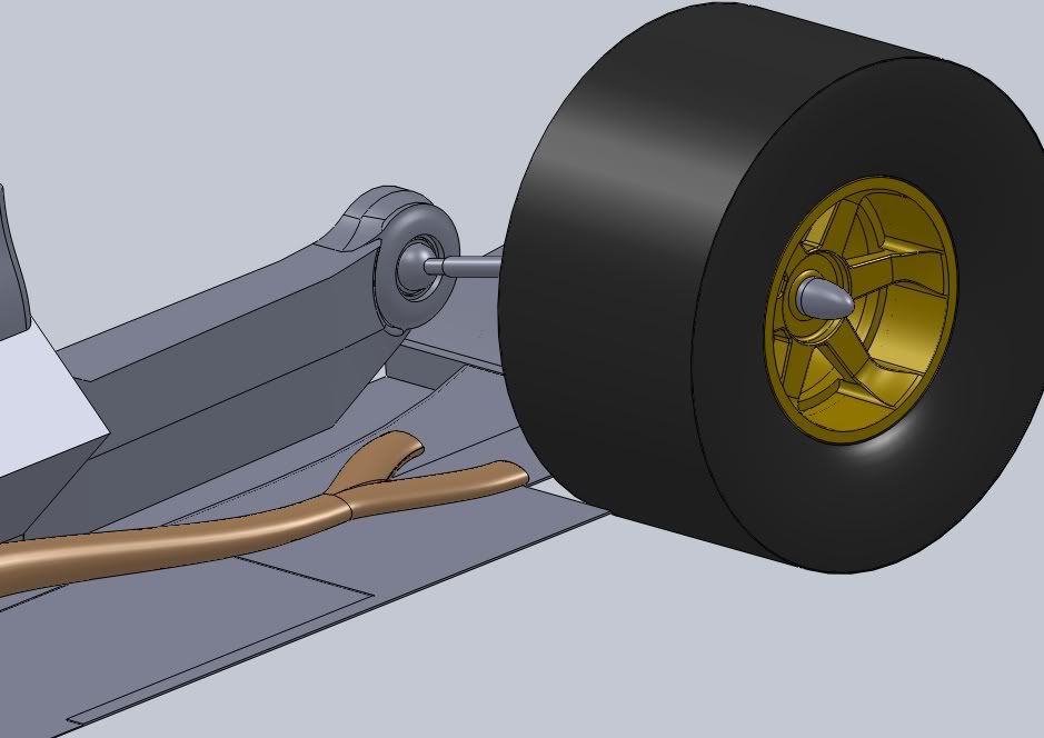
inside joint is a tripode jointringo wrote:i think they use CV joints, but the shaft is splined to allow for length change during suspension movement as i have it here.
I just use one big ball joint to simplify the model. Didnt want to get to detailed with cv joints as i would never finish.
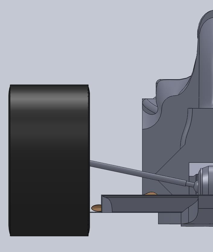
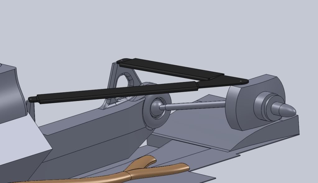
Now that the shaft is in, i realize how extreme the angle is. As the gear box is like the Williams design. The A arms and pull rods are next, but i am finalizing the geometry in MS paint.
Print screens and pasting into MS for doodling makes for good rough work.

Wouldn't you end up with more material in the airflow? Both cables would have to cope with the loads in their given direction, whereas a rod would only have to cope with the max load of the two, if you see what I mean. E.g. by making a rod strong enough under compression it's most likely strong enough (or only needs some small adjustment) under tension.Holm86 wrote:I must say that i like the theory of your cable suspension. IMO it tould work great if you could get cables that wont break.
But there must be some weight penalty?? If i understand your idea correctly there will be 2 dampers and 2 torsionbars at each suspension point?