The hallmark of the Newey cars is efficiency - so much downforce, yet so much top speed, etc.
Each molecule of air must - as it were - know where it is going before it gets there. It is not enough just to steer it in the moment - because ordinary perturbations will disrupt and destroy the effect.
So we should start to analyse this design at the exits, not the entrances. Where is the air to end up, and in what condition?
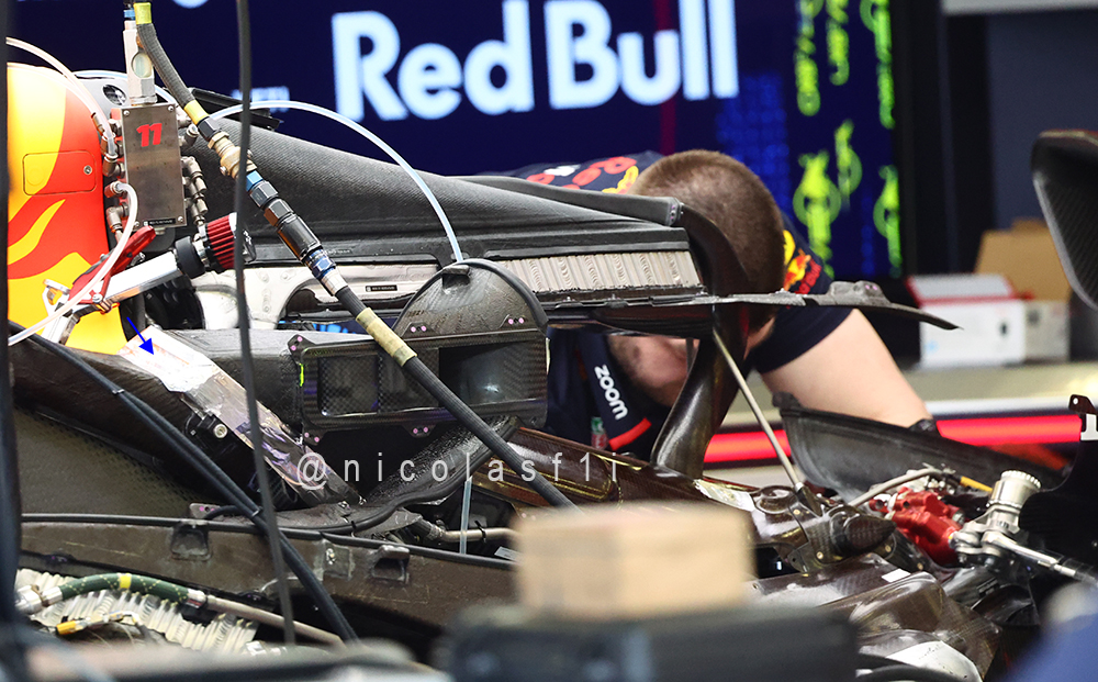
Those vertical sidepod slots, for instance, are brilliant flow conditioners. Amongst other things they’re performing the old Murray McLaren F1 fan trick of “stripping away the boundary layer,” leaving much better-conditioned flows.
But how to stop those slot flows stalling? Well, where would they be useful, and how much energy is required to make them useful?
Those halo inlets likewise are a great way to “suck away” some nasty flow structures, letting the engine provide the heat to energise them (the bend in the duct really doesn’t matter for that), and leaving a cleaner flow down the cannons and over the rear.
Anyhow, just my two cents