firasf1dream wrote:well yes a bit confusing

i had only 1 class in composite and i am the first here in my university CNAM to have ever make a composite project, it's not gonna be only steering wheel, i will make a car f1 model from fiberglass, my degree is in Systems
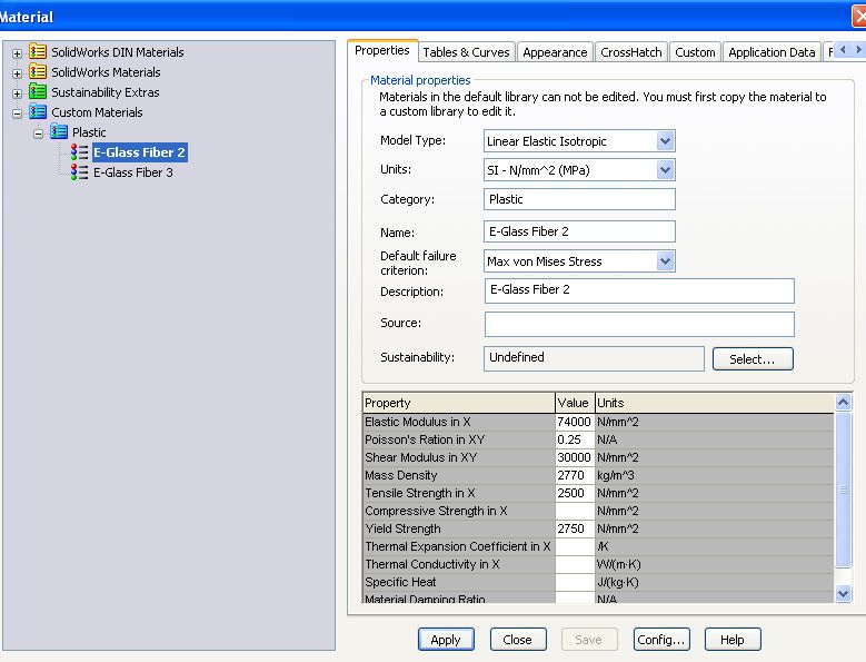
i am really struggling with the material stuff
and for the properties i had hours of research on the internet to be able to find the properties needed and the most reliable ones,
about solidworks solver what is the exact name of this add in ?
and about the oriented in all directions don't you it will work fine ?
Firas, Being a systems guy, I can understand that this is probably quite foreign then. Materials are very difficult, and composites have to be the worst. There is just too much variability based on the layup design and the manufacturing process. It's much easier to use a metal or homogeneous plastic. Knowing that this will not be centered around a mechanical or materials program means you are probably ok to use a lot more assumptions and generalizations. I am sorry for going so technical, I was thinking this was a course based more on mechanical engineering.
Assuming this to be Ud fibers all arranged in random orientations will not work because composites that are continuous fiber are much much MUCH stronger than composites that are chopped fiber (can be over an order of magnitude). This is because of the manner in which the loads are transferred through the resin, the fact that the chopped fibers are relying much more on the resin fiber bond, the fiber density in each direction will not be close to that of a continuous weave with respect to volume fraction...and a host of many other factors.
So my advice to you would be to look up properties of a similar CHOPPED composite and decrease them even more to give yourself margin as has already been suggested by a few of us here. If your design will pass with the strength of just the the resin, then analyze using that too just to detail the amount of margin in your design.
I don't know the name of the solidworks solver...sorry, I use ANSYS almost exclusively.
In short:
-redefine all mechanical loads, as a systems guy you're probably quite familiar with requirements development
-Find the properties of a comparable chopped fiberglass composite (in composite form...not the mat), reduce those properties to give yourself margin, and analyze that. DO NOT USE FIBER STRENGTH OR AN EQUIVALENT Ud COMPOSITE
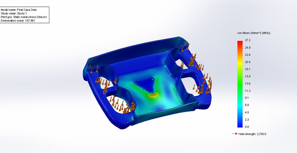
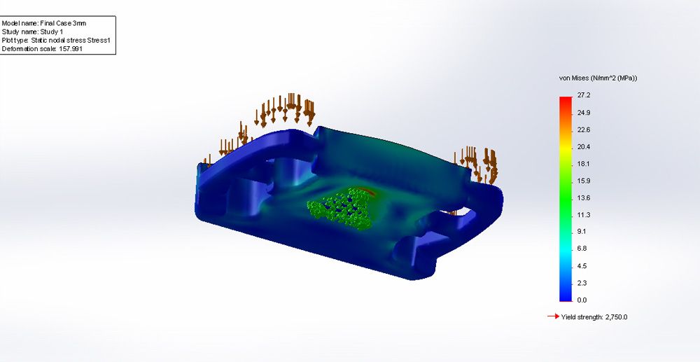
-Run your simulations based on the loads and parameters you just developed
If you want to post up the results and input parameters again, we can probably give it a shakedown to see if it seems in the ballpark.
Another tip, it is actually possible to make the tensile strength of a plastic lower by adding fibers. In the oil and gas industry, we often use PEEK because it can perform in the environment we need. Many times Fiber filled PEEK is weaker than Virgin Extruded PEEK. The fibers are added for different mechanical reasons aside from pure tensile.